-
Description
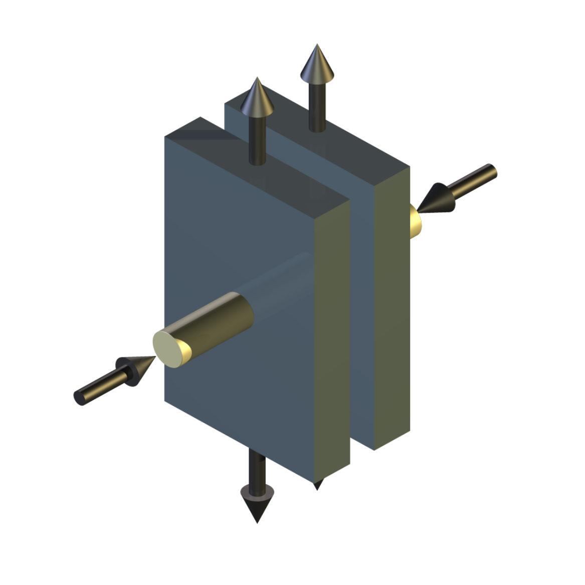
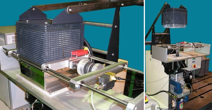
The DN 55 High Temperature Dry Sliding & Fretting Machine comprises a special short stroke, minimum trapped oil volume, servo hydraulic actuator, mounted vertically on a massive cast iron base. The actuator incorporates hydrostatic bearings, which, in combination with the minimized oil volume, allows high frequency and short stroke operation.
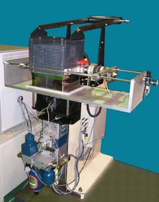
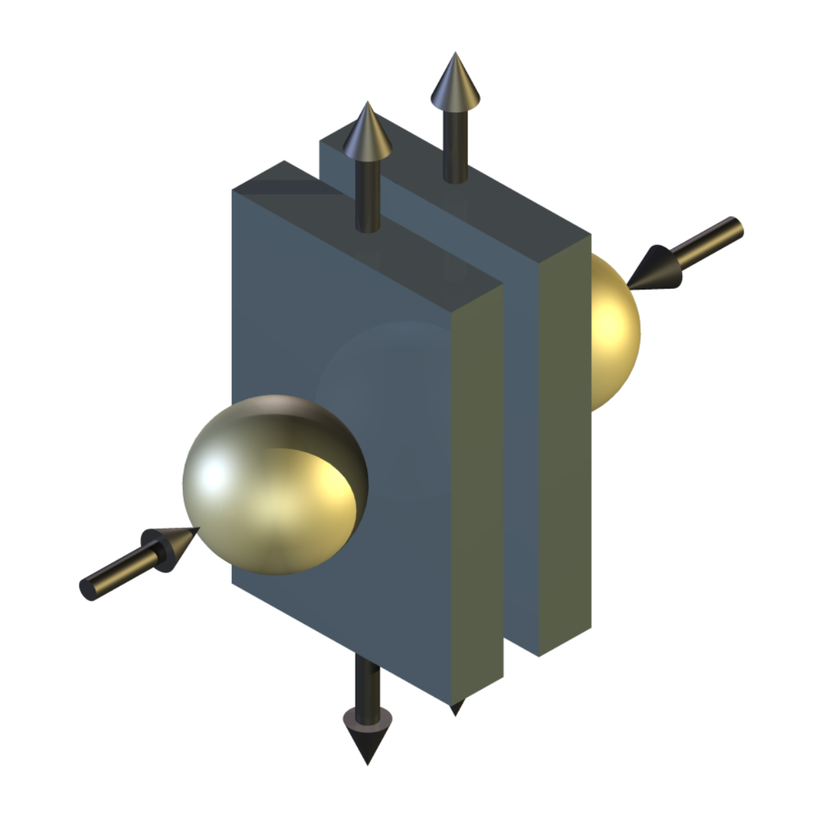
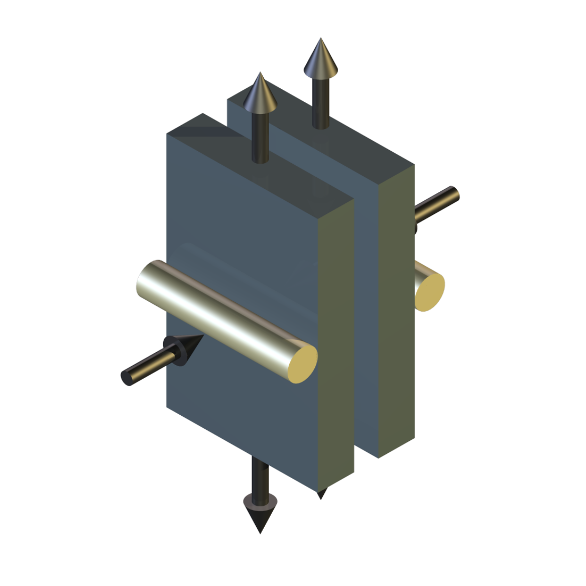
The test assembly is located vertically above the actuator and comprises two fixed specimen arms supported on flexural pivot bearings, which are in turn mounted on linear flexure assemblies. Motion in a vertical direction is restrained by piezo force transducers. As each arm reacts against its own independent transducer, the friction between the each moving specimen and each fixed specimen is monitored independently. This allows two different material pairs to be tested simultaneously under identical conditions of load and temperature.
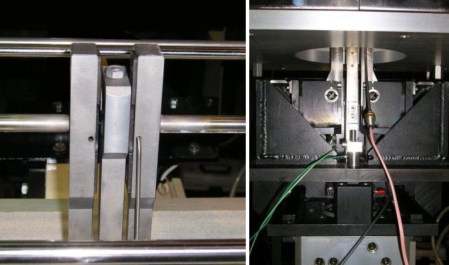
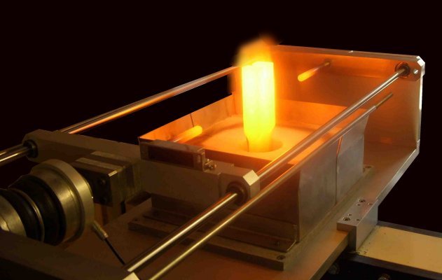
An electrically fired furnace fits over the top of the test assembly, allowing tests to be run under un-lubricated conditions at temperatures up to 1200°C.
Load is applied to either side of the moving specimens by squeezing the two fixed specimen arms together by means of a servo controlled pneumatic bellows assembly, with force transducer feedback. This arrangement ensures that there is no bending moment acting on the moving specimen carrier and the actuator.
The actuator is driven by a Moog super high response servo valve, connected to a high frequency analogue controller, which derives its set points via a 16 bit control and data acquisition card from a standard PC running COMPEND 2020 software. Real time adaptive control features provided within the software allows high precision control of the actuator when working against highly non-linear loads. Sine, square, triangular and random waveforms may be programmed and, depending on the physical capabilities of the hydraulic system, oscillating frequencies up to 500 Hz may be controlled.Displacement Control
The servo actuator, when enabled, is always, for safety reasons, operated under closed loop analogue displacement control with positional feedback from an integral LVDT. An analogue open loop set point is provided to the servo amplifier by the signal generator, which in turn receives an open loop digital set point from the computer control and data acquisition system.
The displacement control loop is subsequently closed in software using a single error correction adaptive control algorithm. This control action operates each time high-speed data acquisition is triggered. The process involves sampling the measured displacement signal and analysing both the peak amplitude and the mid-stroke position. A proportion of the resulting error is added to or subtracted from the digital set point to the signal generator, thus making a single adjustment to both the peak value of the amplitude and the mid-stroke position. Subsequent repeat high-speed data acquisition cycles make further adjustments with the resulting displacement progressively converging on the required value.
Depending on the stroke length, the displacement signal for high-speed data acquisition and adaptive displacement control may be taken either from the LVDT (long stroke applications) or from the capacitance probe (short stroke applications).Frequency Control and Waveform
The frequency is set digitally either manually from the on-screen display or from the test sequence file. Similarly, uniform waveforms (sine, triangular or square) may be toggled from the screen or set within the test sequence file. Pre-recorded random waveforms may also be toggled, but under these circumstances, the adaptive control functions must, for obvious reasons, be disabled.
Signal Processing and Data Acquisition
Low-speed data, such as temperature, load and r.m.s. parameters, may be stored to hard disk. At the end of a test this data may be manipulated for calculation or graphical presentation using standard spreadsheet software.
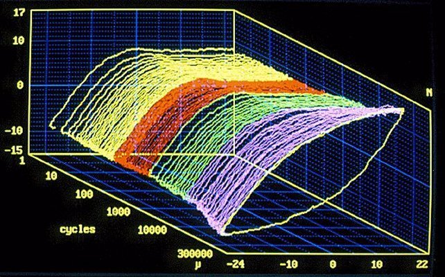
High-speed data acquisition may be triggered either manually from the computer screen or automatically from a test sequence file. The operator may select the number of channels to be recorded, the sampling frequency and the number of samples. Each burst of high-speed data is stored in an independent data file. If triggered automatically through a test sequence file, each burst of high-speed data is stored into a new file, which is automatically time stamped, with a hyperlink automatically generated between the appropriate point in the low-speed data file and the corresponding high-speed data file.
Impact Sliding and Impact Fretting Tests
For impact sliding and fretting tests, the standard fixed specimens are replaced by wedge shaped specimens. The moving specimen is withdrawn from contact and the fixed specimens are loaded against a stop with a pre-set force applied by means of the pneumatic bellows. To perform a test, the moving specimen is brought into contact with the fixed specimens under velocity control. Adaptive control functions in the software allow peak to peak tuning of the displacement in order to achieve either a required displacement or a required impact force.
Impact and Hertzian Fretting Tests
For impact and Hertzian fretting tests, to twin fork tooling is replaced by a single fixed specimen mounting system. Impact tests are performed with the fixed and moving specimens coming in and out of contact. Hertzian fretting tests are performed with the specimens in continuous contact.
DN 55/1 Small Perturbation Signal Generator
This optional additional signal generator and signal analysis system allows combined sliding motion with co-axial vibration to be generated. The standard servo amplifier incorporates a summing junction on the input stage with dual inputs. This means that with the addition of a second signal generator, two separate signal inputs, one low frequency and long stroke and one high frequency and short stroke, can be combined, thus producing reciprocating motion with superimposed vibration from a single servo hydraulic actuator.
-
Technical Specifications
Type of contact: Ball/Flat Flat/Flat Line/Flat Maximum Specimen Diameter: 20 mm Type of Movement: Sine, Square, Triangular and Random Maximum Load: 2000 N Maximum Friction Force: +/-2000N Stroke – continuously variable: 10 microns to 20 mm Frequency: 0.1 Hz to 200 Hz Environment: Dry Temperature: Ambient to 1200°C Super High Response Servo Valve: 12 l/min Actuator Bearings: Hydrostatic Dynamic Load: 5.7 kN Static Load: 8.6 kN Hydraulic Power Pack: 12 l/min at 250 bar High Speed Interface: PCI bus Resolution: 16 bit Number of Input Channels: 1 to 16 Maximum Data Rate: One channel at 250 kHz Interface: Serial Link Interface Module Software: COMPEND 2000 DN 55/1 Small Perturbation Signal Generator Type of Movement: Sinusoidal sliding stroke with co-linear superimposed sinusoidal perturbation Sliding Motion: Maximum Stroke: 20 mm (Amplitude: 10 mm) Type of Movement: Sinusoidal Frequency (FS): 0 to 5 Hz Vibration Motion: Stroke/Frequency: 200 microns (Amplitude 100 microns) @ 0 to 200 Hz 100 microns (Amplitude 50 microns) @ 0 to 300 Hz Frequency (FP): 0 – 300 Hz Control Requirements: FP must be greater than FS x 20 Controlled Parameters Frequency Stroke Load Temperature Test Duration Measured Parameters Frequency Stroke Load Friction Temperature Services Electricity: 220/240V, single phase, 50 Hz, 7.5 kW 110/120 V, single phase, 60 Hz, 7.5 kW Mains water and drain: 10 l/min (typical) -
Index Tags
-