-
Description
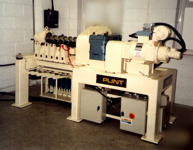
The test rig incorporates 6 test stations, with test rings of 100 mm diameter locked onto a single shaft. The shaft may be continuously rotated or oscillated. The sliding speed range is covered by a direct coupled dc motor and 20.9:1 or 195:1 reduction gearboxes. Oscillating tests are achieved by using an adjustable throw crank mechanism coupled between the 20.9:1 reduction gearbox and the specimen shaft.
Test Specimens
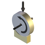
Test specimens may be conformal or non-conformal blocks of material or sections of plain bearings. The six ring samples are a sliding clearance fit on the test shaft and are locked in place by an axial force generated by a hydraulic nut. The test specimens are mounted inside sealed reservoirs to allow for fluid recirculation. The seals will allow up to 5mm of movement that is due to wear in the contact.
The loading system uses hydraulic cylinders to achieve the full-scale values. The applied load is measured by strain gauge force transducers mounted directly beneath the specimen carrier assembly. Low loads are achieved using dead weights through a 5:1 lever, which acts independently from the hydraulic system. The hydraulic cylinders are fitted with spring returns for rapid removal of applied load. Each load station is provided with an automatic unloading system triggered by either a physical micro-switch (wear limit) or from the controller at a preset limit of temperature or friction (if instrumentation is fitted).Instrumentation
All test stations are adaptable to allow the following measurements:
- friction force
- wear
- block sample temperature
- fluid temperature – circulation and cooling
Control and Data Acquisition
Control and data acquisition are implemented via host PC running COMPEND 2020 Windows compatible software, in conjunction with a Phoenix Tribology USB micro-controller interface.
Automatic control is implemented via user programmable test sequences. Manual control is implemented using on screen toggles. Data is stored to hard disc in either .csv or .tsv file formats. -
Technical Specifications
The basic performance envelope is defined by the following practical material or application limits. For all six stations the limits are as follows: Maximum Bearing Pressure (for all six stations) 120 MN/m2 Limiting PV Value 10^6 N/m2 . m/s Maximum Sliding Speed continuous rotation 10 m/s Maximum Sliding Speed oscillation 0.55 m/s Minimum Sliding Speed for low loads 5 mm/s or less Minimum Size for Test Specimen 25mm x 25mm In addition the test rig has the capacity to operate 2 test stations at higher values of pressure and sliding speed, with the same limiting PV value: Maximum Pressure (two end stations) 200 MN/m2 Maximum Sliding Speed 20 m/s For oscillating tests: Maximum Amplitude +/- 30° Maximum Frequency 3.3 Hz (200 rpm) Overall machine limits: The overall limits of the machine are defined by the maximum load on the shaft, the power of the motor and the maximum torque available at each speed. Maximum Power 12 kW Torque at 3,000 rpm 40 Nm Gearbox Ratios: 20.9:1 and 195:1 Maximum Total Load on Shaft 100,000 N Controlled Parameters Rotational Speed Loads Test Duration Measured Parameters Rotational Speed Friction Torques Loads Temperatures Test Duration Friction Coefficients -
Applications
bearing friction block on ring dynamic friction hydrodynamic lubrication journal bearing marine bearings plain bearing materials plastics polymers PV diagrams -
User List
Launched 2002
Not disclosed
-
Download the Machine Leaflet