-
Back-ground
The latest design is an updated and enhanced performance version of an original machine, first manufactured in 2008. The design is ATex Zone 2 compliant.
Description
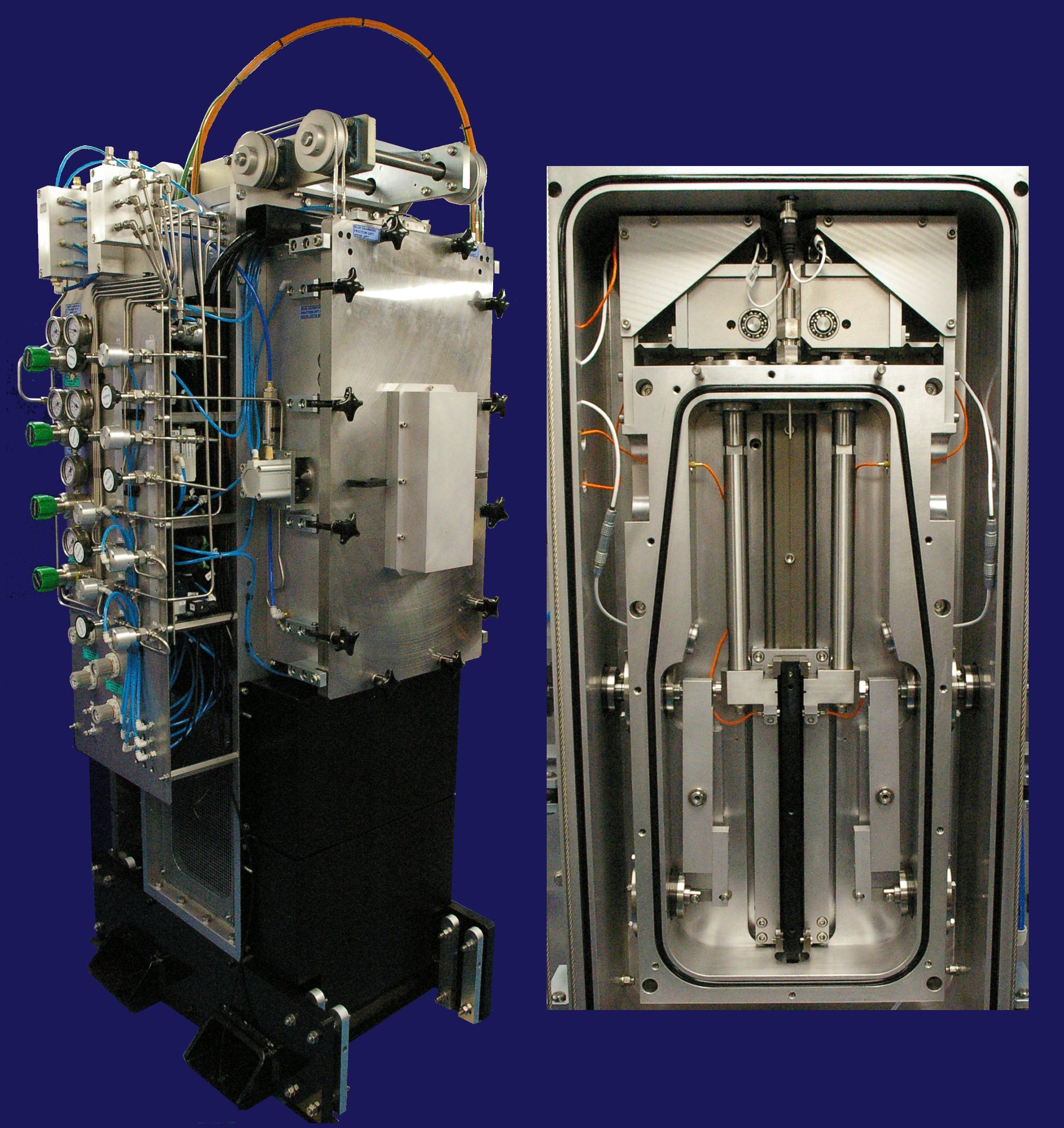
The test rig incorporates two crank assemblies, driven by a variable speed motor, providing reciprocating motion, in two separate test chambers. The reciprocating assemblies are 180 degrees out of phase, providing a degree of primary balancing.
The test chambers are of compound design, comprising an inner, hydrogen, chamber mounted inside an outer, nitrogen, chamber. Each inner chamber provides locations for two test specimen pairs, providing a total of four test stations.
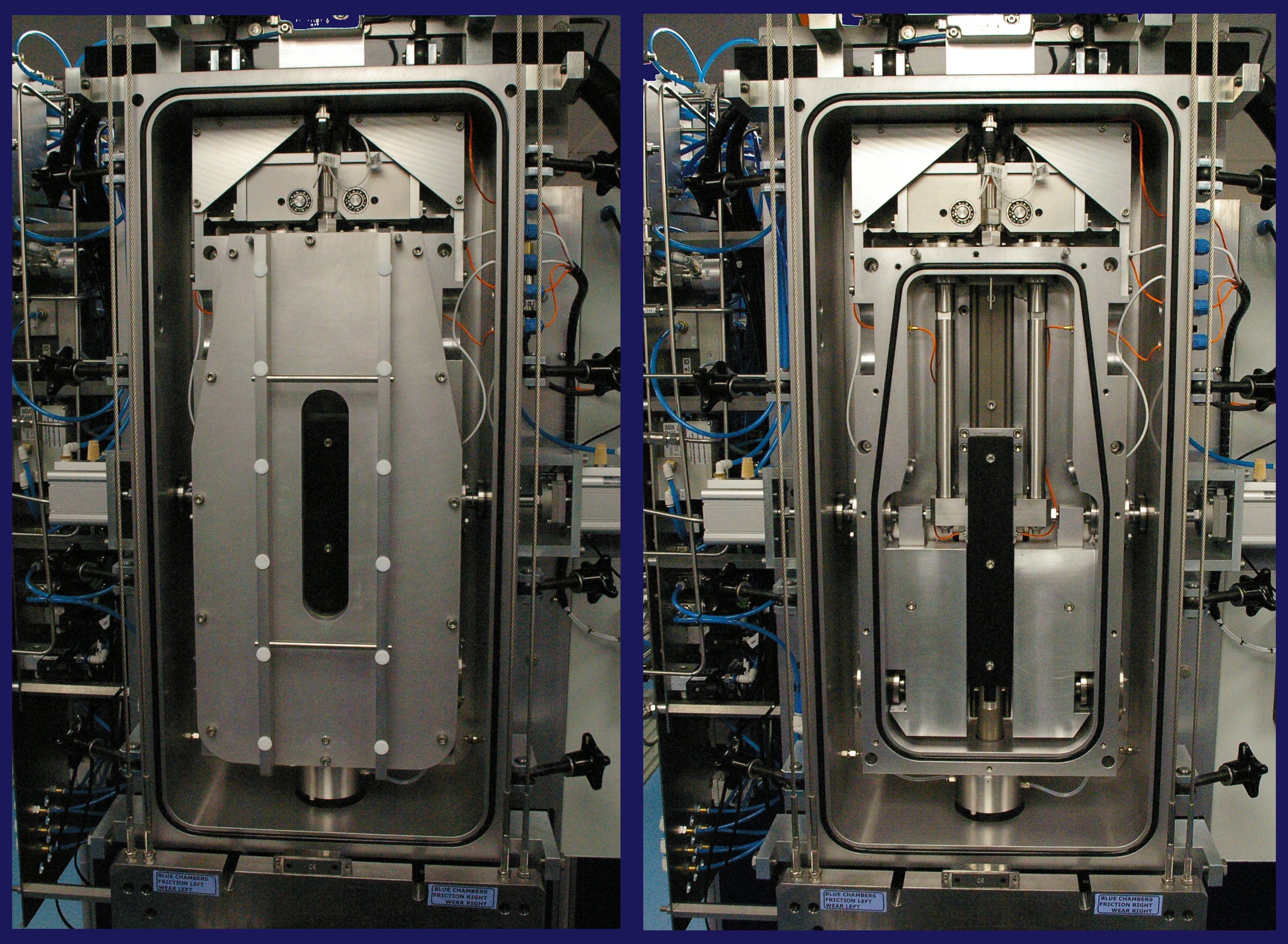
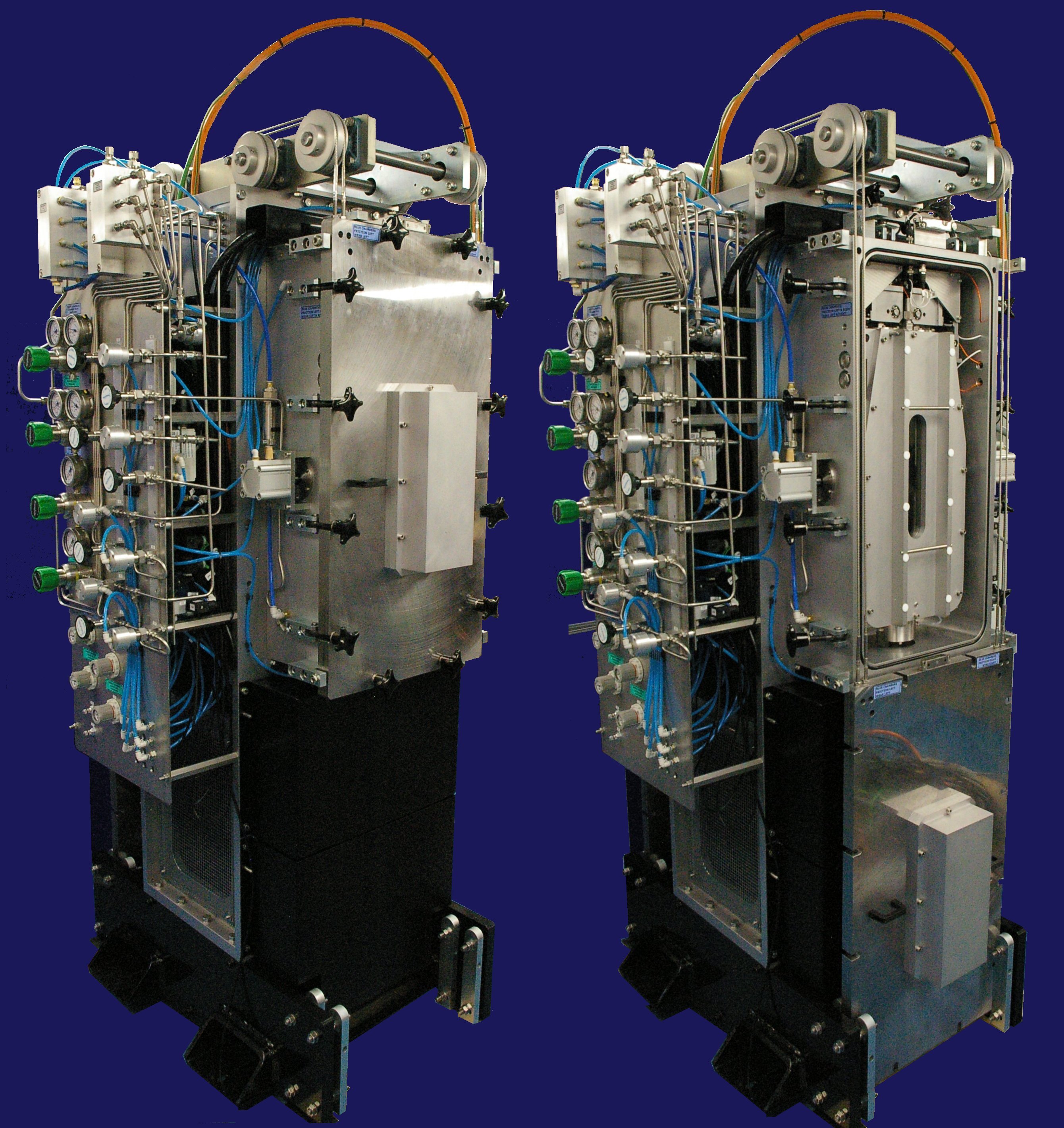
The inners chambers have removable, high-strength, aluminium doors, fixed by cap-head screws. The outer chambers have removable steel doors, secured by hinged pressure vessel clamps. Because of their mass, counter-balance mechanisms are provided, to aid with raising and lowering the outer doors.
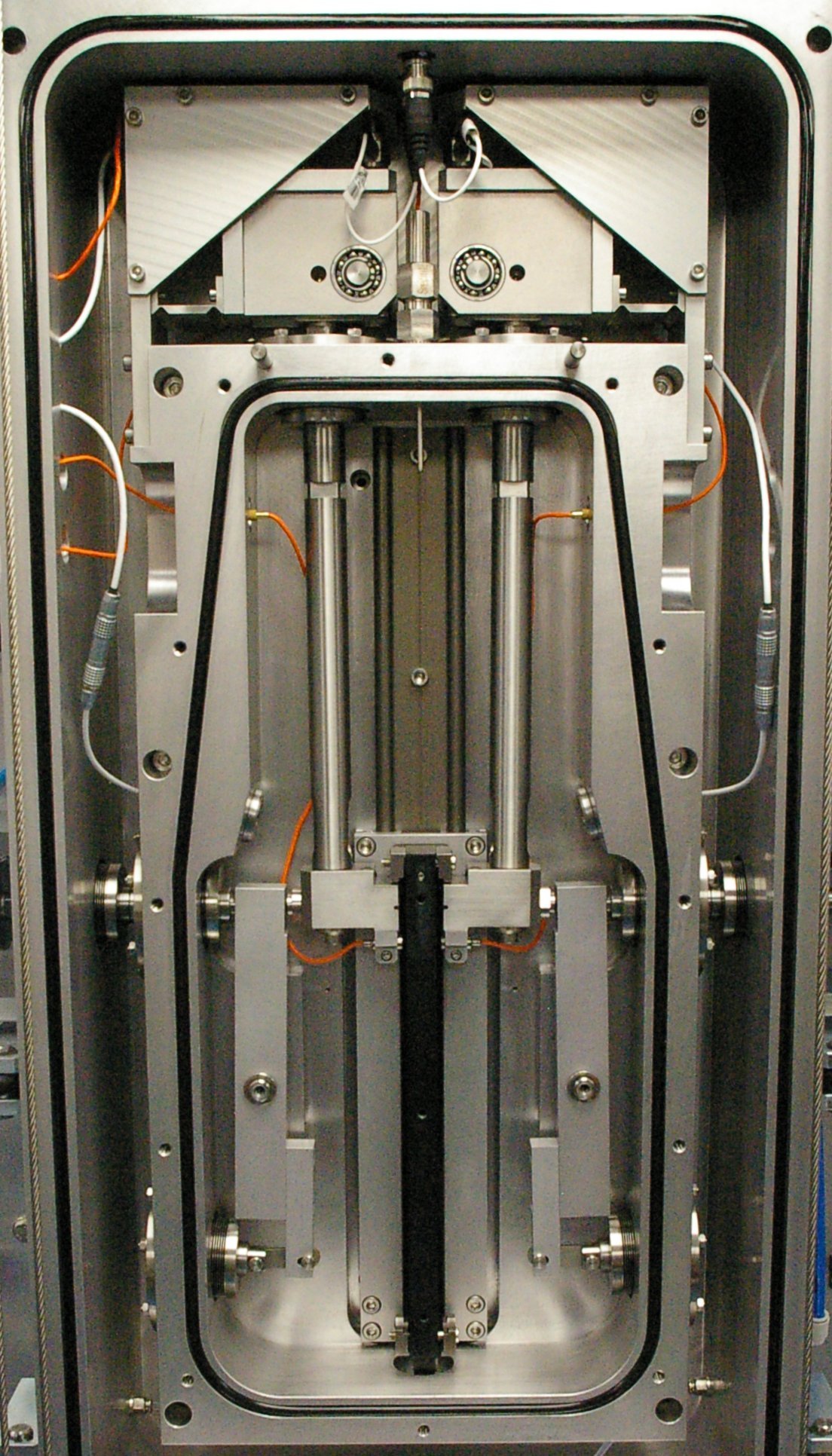
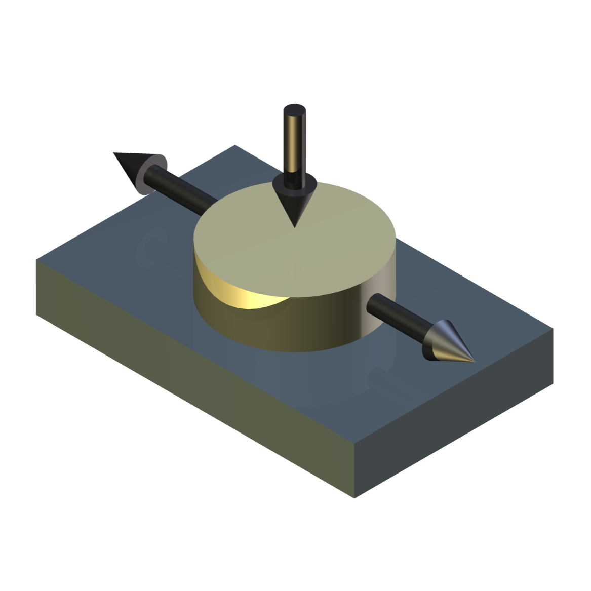
Two fixed specimens, mounted in spherical seat self-aligning specimen holders, are loaded on either side of a reciprocating specimen plate carrier, such that no net normal load is applied to the reciprocating assembly.
Friction and Wear
Each fixed specimen is carried on a flexure mounted articulated arm, which is restrained in the direction of the friction force by a piezo force transducer. This allows friction to be measured. Movement of the fixed specimen relative to the moving specimen in monitored by means of a capacitance displacement gauge, to indicate wear.
Load
Load on each specimen pair is applied by means of a servo pneumatic cylinder, with a force transducer for load force feedback, to the servo control system. The load force is transmitted through the walls of the two chambers through edge welded stainless steel bellows.
The inner chamber incorporates an additional bellows in conjunction with a lever mechanism to compensate for pressure generated forces on the load bellows.Non-contact Heating
In addition to frictional heating, the moving specimens are heated by means of infra-red emitters mounted on the outside door of the outer chamber, focusing through high-performance glass-ceramic windows. Plate specimen temperatures are measured with non-contact infra-red sensors.
Reciprocating Motion
The reciprocating motion is transmitted through the chamber walls via linear seals, of a type typically used in gas compressors. Two seal assemblies are provided for each compound test chamber, with an outer seal assembly between atmosphere and nitrogen and an inner seal assembly between nitrogen and hydrogen.
Sealing
Each assembly incorporates tandem sealing ring cassettes, with one seal pack on the high-pressure side and one on the low-pressure side, with a small void in between. For the inner seal, between the hydrogen chamber and the nitrogen chamber, this void is pressurised with nitrogen and continuously purged. Controlling the pressure of the nitrogen allows the hydrogen leakage rate through the seals to be controlled and the continuous purging ensures that any leakage is safely discharged.
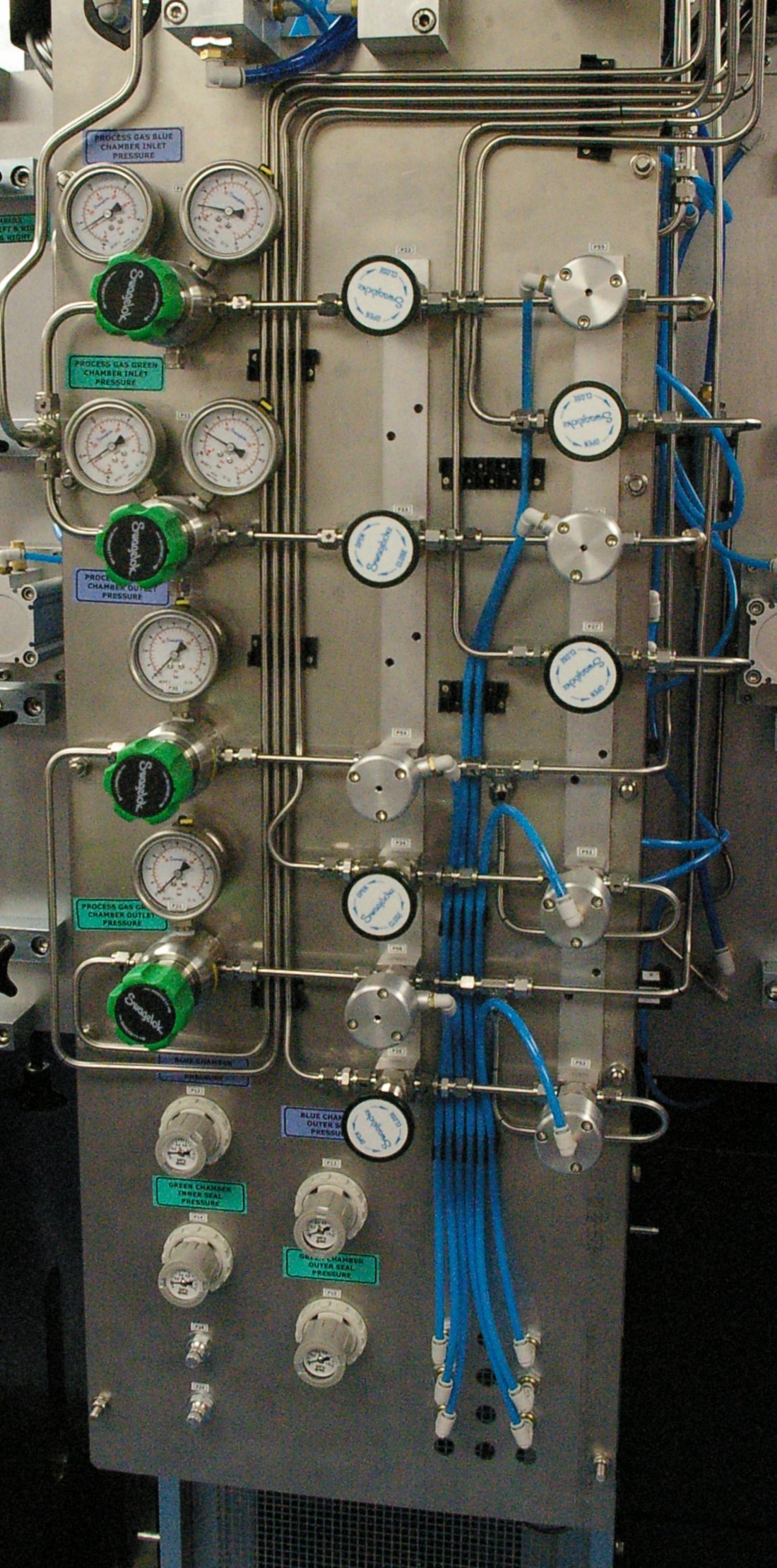
Gas Control System
Hydrogen and nitrogen gas pressures in the chambers are independently set and controlled, with hydrogen supply and relief pressures set manually. Nitrogen supply pressure to the inner seals is also set manually. Nitrogen pressure to the outer chamber and for purging both chambers is automatically controlled via a servo valve. A separate PLC is provided to control the gas supply and vent circuits, via solenoid valves, and provides automatic control of purging, leak testing, charging with process gas, and safe venting of the system.
Control and Data Acquisition
The machine is floor standing with integral control unit incorporating a Phoenix Tribology USB Serial Link Interface Module. This is connected to a rack mounted PC with COMPEND 2000 sequence control and data acquisition software installed. The system provides sequence control of load, frequency and temperature plus data acquisition of measured parameters.
-
Technical Specifications Test Chamber Gases: H2 Natural Gas Air N2 Containment Chamber Gas: N2 Maximum Test Chamber Pressure: 5 bar Maximum Purge Pressure: 5 bar Test Pressure – Containment Pressure: 0.5 bar (Typical) Contact Configurations: Area Contact Line Contact Ball on Flat Area Contact Specimen: Ø18 mm with hemispherical seat Minimum Load: 30 N Maximum Load: 500 N Maximum Friction Force: 200 N Frequency/Stroke: 50 mm at 20 Hz 100 mm at 10 Hz 150 mm at 7.5 Hz 200 mm at 5 Hz Maximum Frequency: 20 Hz Maximum Plate Temperature: 150 °C Heating: Non-contact Radiant Load Control: Servo Valve x 2 Load Feedback: Strain Gauge Load Cell x 2 Friction Force: Piezo Transducer x 4 Wear Measurement Capacitance Probe x4 Plate Specimen Temperature: Pyrometer x 4 Inner Chamber Temperature: PT 100 x 2 Chamber Pressure: Pressure Transducer x 4 Motor: 7.5 kW a.c. servo motor and drive Interface: USB Serial Link Interface Module Software: COMPEND 2000 COMPEND Controlled Parameters Frequency Test Duration Load Chamber 1 Specimen Temperature – Chamber 1 Nitrogen Pressure – Containment Chamber 1 Load Chamber 2 Specimen Temperature – Chamber 2 Nitrogen Pressure – Containment Chamber 2 PLC Controlled Parameters Purging Leak Testing Charging with Process Gas Venting Manually Set Parameters Reciprocating Stroke Length Hydrogen Pressure Inner Seal Back-pressure (Nitrogen) Measured Parameters Frequency Test Duration Load x 2 Friction x 4 Wear Displacement x 4 Specimen Plate Temperature x 4 Chamber Pressure x 4 Chamber Temperature x 2 Services Electricity: 380/415V, three phase 50/60 Hz, 13 kW Process Gas System: Not included ATex Rating The machine, drive motor and associated instrumentation are ATex rated. The power module and PC control and data acquisition system are not ATex rated. It follows that these items must be installed outside any ATex rated test cell, with suitable ATex rated connections between the operator work-station and the test cell. -
Overview Videos
Machine Overview
-
Index Tags
-
Download the Machine Leaflet