-

Background
Numerous test rigs have been devised for investigating valve seat recession, ranging from motored engine and cylinder head rigs to devices based on servo hydraulic actuators.
The rigs based on engines and cylinder heads typically use standard cam shafts for generating the motion. The cam designs are invariably constant acceleration as opposed to constant velocity devices, hence a given velocity is only achieved at a specific valve displacement.
At the frequencies and amplitudes required for a sensible test rig, servo hydraulic actuators will typically be capable of generating only sinusoidal motion, hence, once again, a given velocity is only achieved at a specific displacement.
It is generally agreed that valve seat recession is dependent on the velocity of the valve at impact with the seat. Clearly, the velocity of the valve at any part of the cycle preceding impact is of no relevance. It follows that any device that uses either a constant acceleration type cam or a servo hydraulic actuator to generate the motion, will require very precise adjustment of the relative position of valve and seat in order to achieve the required impact velocity. Furthermore, as wear takes place, the position of impact relative to the motion will change and hence the velocity of impact will change.
The logical conclusion has to be that instead of using a constant acceleration cam the rig should use a constant velocity cam, so that it does not matter where the impact occurs relative to the motion, the velocity will always be the same. With an actuator, logically one should use a saw-tooth as opposed to a sinusoidal motion; this is achievable, but not at anything other than modest frequencies.
A constant velocity cam is of course only possible in theory, as the change of direction at TDC and BDC would necessarily require infinite acceleration.Description
The TE 35 Valve Impact Rig uses cams that are constant velocity over at least sixty degrees of rotation, with profiles designed to give variable velocity either side of TDC and BDC. Impact velocity, which, as with other rigs, varies with rotational speed, is essentially constant over a significant part of the valve motion.
Standard 4 mm Lift Cam
The 4 mm lift cam is constant velocity over 60 degrees of rotation, corresponding to a displacement of between 1 mm and 3 mm. Providing the impact occurs between 1 mm and 3 mm displacement, the velocity will be constant at a given rotational speed.
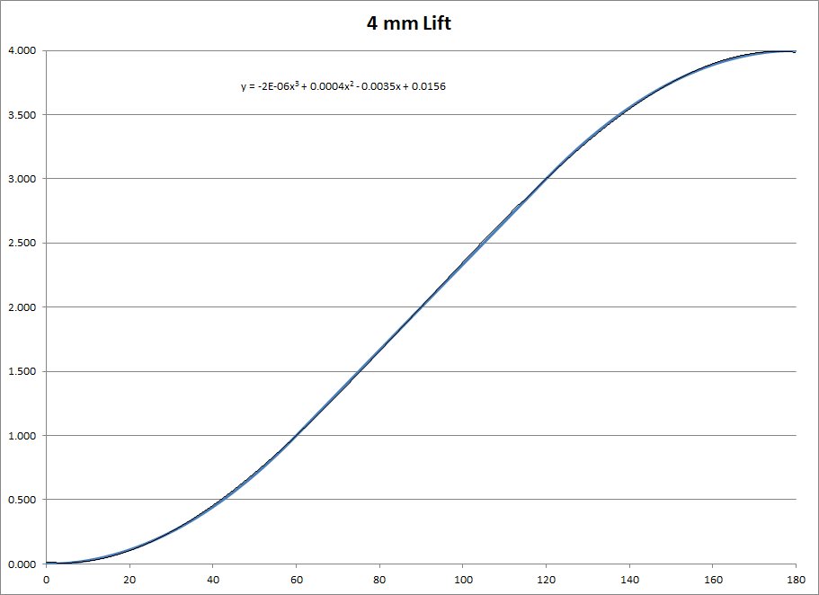
The relationship between velocity and rpm with the 4 mm cam, between 1 mm and 3 mm displacement, is:

Velocity (mm/s) = 0.2 x rpm
Hence, at 2,000 rpm, the impact velocity will be 400 mm/s.
Standard 6 mm Lift Cam
The 6 mm lift cam is constant velocity over 84 degrees of rotation, corresponding to a displacement of between 1 mm and 5 mm. Providing the impact occurs between 1 mm and 5 mm displacement, the velocity will be constant at a given rotational speed.
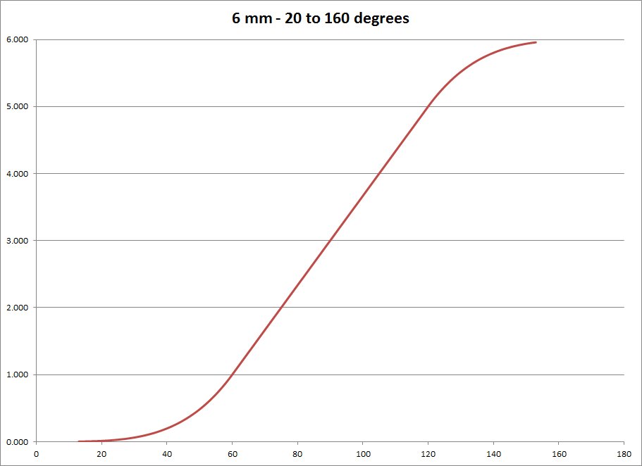
The relationship between velocity and rpm with the 6 mm cam, between 1 mm and 5 mm displacement, is:
Velocity (mm/s) = 0.2857 x rpm
Hence, at 2,000 rpm, the impact velocity will be 571 mm/s. At 2,800 rpm, an impact velocity of 800 mm/s is achieved.
Follower loci and cam profiles are of course very different from standard automotive cams.

Valve Spring and Driving Force
The use of specially designed cams means that the maximum velocity of the valve never exceeds the required impact velocity.
With a conventional automotive cam shaft, the valve, when open, moves much faster than the impact velocity, in other words, the valve is decelerating as it approaches the point of impact. A direct consequence of this is that such test rigs have to use high spring forces, simply to accommodate the higher velocities associated with the motion of the valve, when it is open, in other words, during a part of the cycle that is of no importance. The use of higher spring forces naturally leads to higher dynamic forces on the drive system and the requirement for larger drive motors.
By contrast, with a near constant velocity cam, the closing spring force and the drive capacity requirements are substantially reduced, because it is not necessary to drive the valve at the maximum velocity achieved in the engine, just at the required impact velocity in the test rig. The cam, spring and driving system are designed to do only what is required.
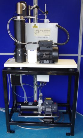
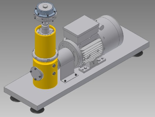
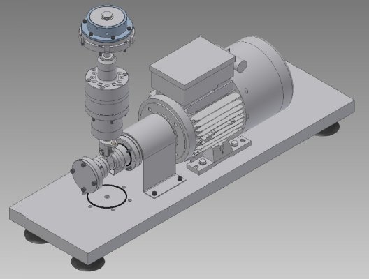
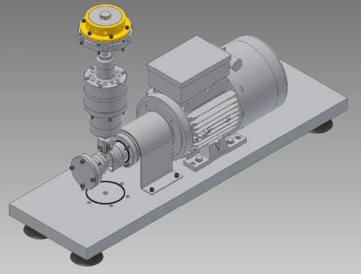
Machine Structure
The machine is mounted on a frame, which incorporates a control cabinet, hot air jet heating system and lubrication service module. The machine is mounted on rubber isolation mounts and comprises a variable speed a.c. motor connected via a flexible coupling to the test assembly camshaft.
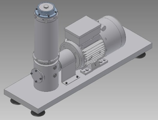
The test assembly comprises a fixed “bottom end” and an adjustable position, valve and seat positioning assembly. This upper assembly interfaces with the bottom end assembly via a large diameter 2 mm pitch thread.
The relative position of the upper and lower assemblies is adjusted by rotating the upper assembly. This allows setting of the valve clearance and allows valves of different lengths to be accommodated. A locking ring is provided for setting the required position.

The bottom end assembly supports the cam shaft, which is mounted in rolling element bearings. Motion is transmitted via a needle roller cam follower, mounted in a linear guide bush. A push rod, with a light duty spring, maintains contact between the follower and the cam and transmits motion to the valve.
The valve and seat assembly is fitted at the top and incorporates a heater block for heating the valve seat.
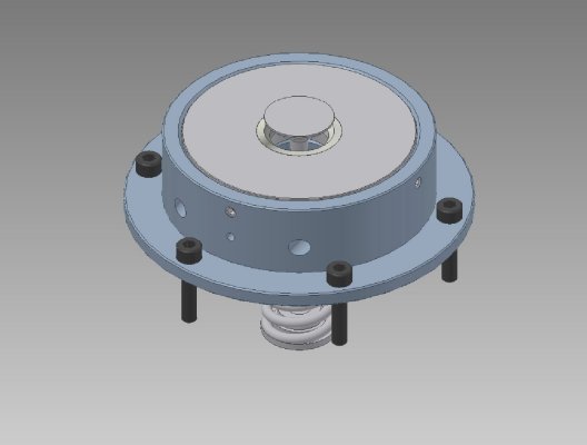
A standard valve guide blank is used, bored and reamed as required, to match the valve to be tested. Typical guide O/D is 12 mm, with bore and length adjusted as required.
The guide, seat, valve and spring are installed as normal. A screw adjustable sleeve at the non-collet end of the spring allows the spring pre-load to be adjusted. A spring pre-load force of 200 to 300 N is typically sufficient to achieve satisfactory operation.
Valve Guide and Stem Seal
Unlike a conventional cam-follower driven system, minimum lubrication is required near the valve and seat assembly, with the majority of lubricant confined to the bottom end sump. This essentially eliminates the requirement to use valve stem seals, simplifying the test set up.
Setting Impact Position
The impact position is set with the cam follower at BDC. The upper assembly is rotated downwards onto the screw thread until the valve just starts to lift. In this position, the valve would lift the full cam displacement at TDC.
The upper assembly is then rotated in the opposite direction, upwards, to give the necessary valve clearance. One complete rotation will set a valve clearance of 2 mm, meaning that impact occurs during the constant velocity part of both the 4 mm and 6 mm cams. No fine adjustment is required.
Valve and Seat Heating
The valve is heated by hot air jet, with temperature sensed by pyrometer. The seat is heated with electrical resistance heaters, with temperature sensed by thermocouple.
-
Technical Specifications
Maximum Rotational Speed: 3,000 rpm Maximum Impact Velocity at 3,000 rpm: 4 mm cam: 600 mm/s 6 mm cam: 857 mm/s Maximum Valve Temperature: 450°C Maximum Seat Temperature: 350°C Valve Lengths: Smallest: 85 mm Largest: 170 mm Services Electricity: 220/240 V, single phase, 50/60 Hz, 7.5 kW -
Overview Videos
-
Index Tags
impact sliding special applications valve impact valve recession valve seat impact valve seat materials