-
Background
Dynamic bearing fatigue rigs can be divided into two basic performance categories:
• Pulsating Alternating Load – Full Wave Load Cycle
• Pulsating Load Between Zero and Maximum – Half Wave Load Cycle
Dynamic loading has been generated both mechanically and hydraulically.Full-wave Rigs
The original “Underwood” machine was patented in 1945 and is still in use in various guises. A cyclic pulse, generated by rotating out-of-balance masses, is applied to a test bearing. The bearing is loaded in both directions and the magnitude of the pulse varies with rotational speed.
The Amsler “Pulsator” has been used to generate cyclic loads on bearing rigs. The natural frequency of the specimen assembly, which is varied by adding or removing weights, is set in vibratory motion by an electro-magnetic drive. It is reliable, but with limited flexibility, and obviously only operates at the resonant frequency, which is typically 80 Hz.
Neither machine allows direct control of the resulting dynamic load on the test bearing. To address this problem, various servo dynamic bearing test rigs have been designed. These machines use high dynamic force servo actuators, usually fitted with multiple super high response Moog servo valves and with high speed adaptive control software. Capital, running and servicing costs are significant.Half-wave Rigs
The “Sapphire” machine (Glacier Metals – 1958) is a half-wave actuator rig. A journal bearing sample is mounted on an eccentric shaft with a connecting rod attached to a dashpot, producing the equivalent of a badly pulsing pump. On the “induction” stroke, oil is drawn into the “pump” through a non-return valve and on the “compression” stroke oil is discharged against the resistance of a pressure relief valve. This is an ideal and simple method of generating a pulsating load, the magnitude of which is controlled by adjusting the relief valve setting.
Description
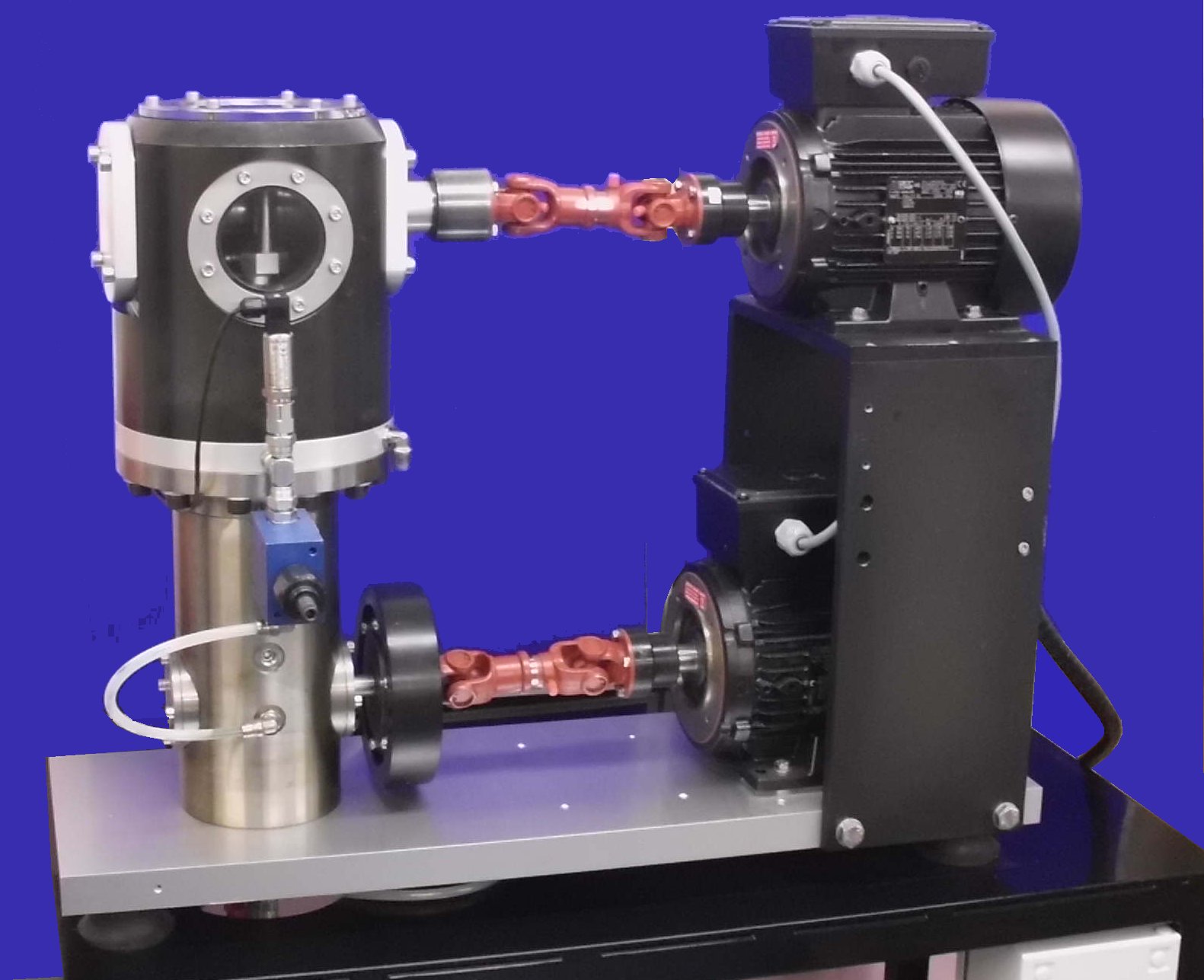
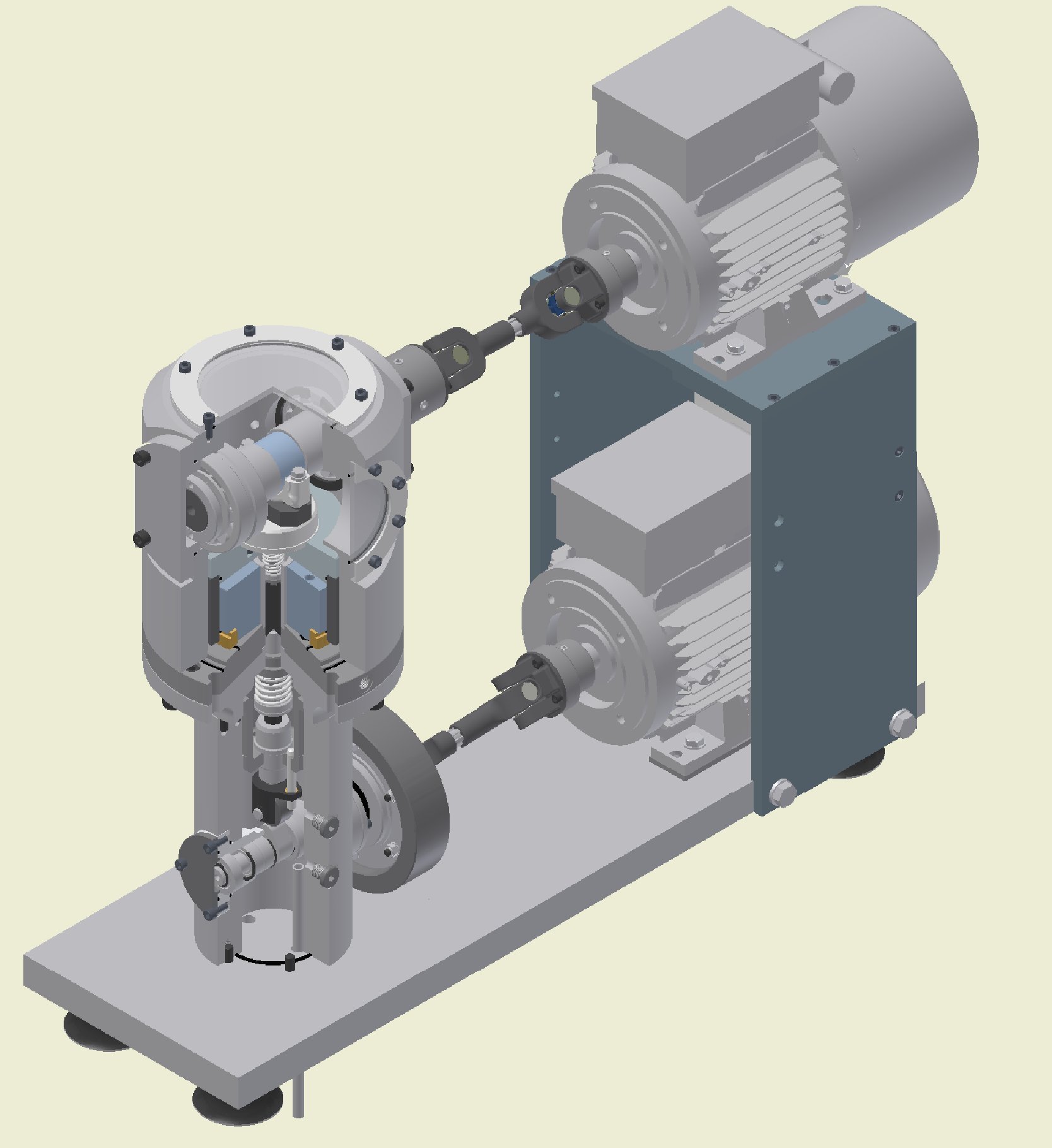
TE 36 Dynamic Bearing Fatigue Rig is essentially a deconstructed “Sapphire” machine, in which the rotation of the test shaft and the generation of the pulsating pressure have been separated, hence resulting in a rig with two separately controlled motors.
The upper motor drives the journal bearing test shaft; this is a plain shaft. The speed of the upper motor can be varied as required to allow different lubrication regimes to be achieved in the test bearing.
The lower motor drives a cam shaft, which actuates a spring loaded piston, producing the equivalent of a simple plunger pump.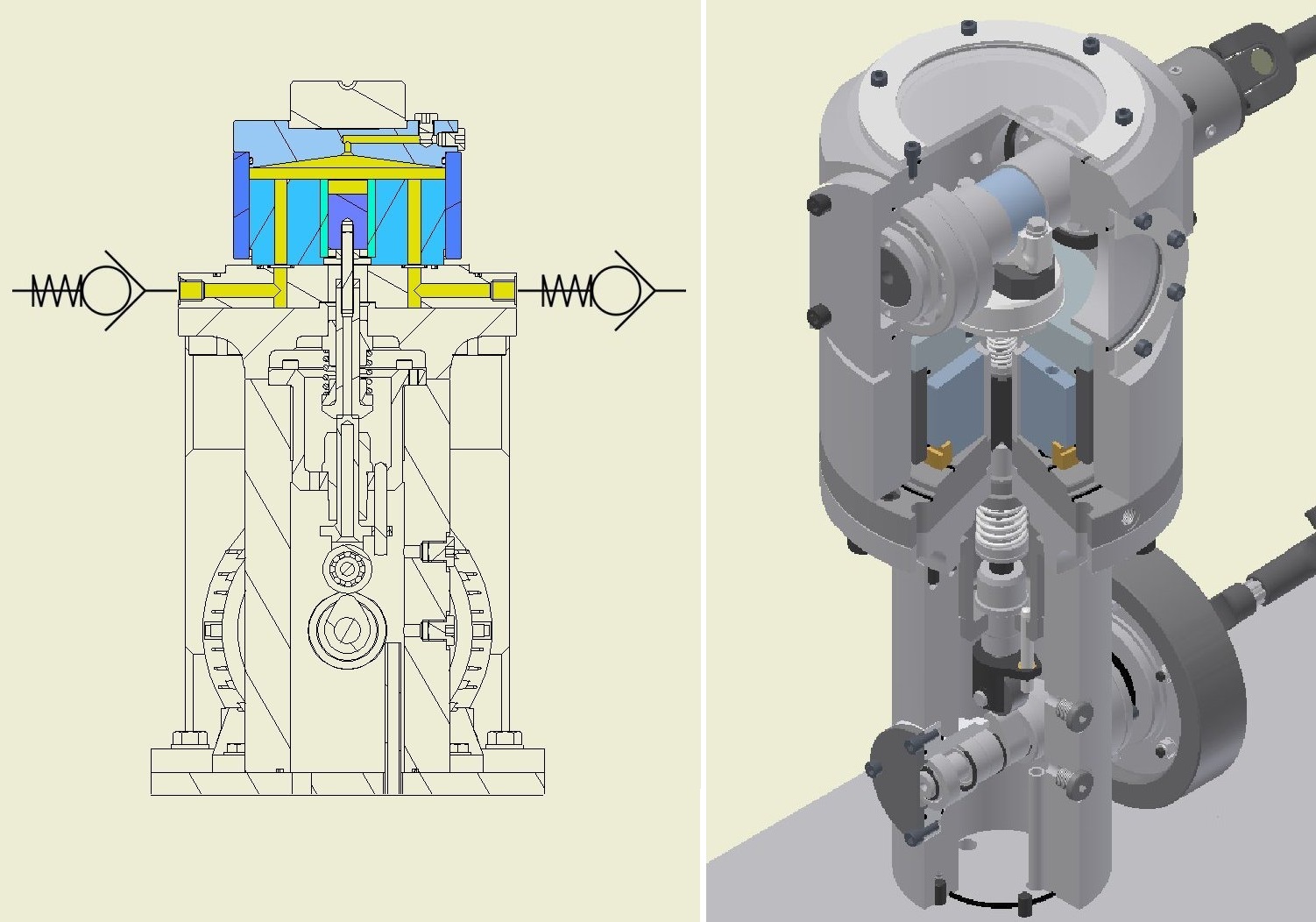
The piston, which is 25 mm diameter, runs in a bore in the centre of a larger piston, over which is mounted a closed, floating cylinder. The larger piston has a bore of 125 mm, giving 25:1 force intensification between the small and large pistons.
A unique feature of the unit is that the high hydraulics pressures are generated and thus contained within the piston assembly and the resulting high dynamic forces are reacted entirely within the test assembly. There is no requirement for external high pressure piping and no requirement for a high stiffness, massive, frame assembly.Dynamic Performance
The operating range for the cam drive is at rotational speeds between 600 and 1200 rpm, in other words, between 10 and 20 pulses per second. With the current cam design, pulses at 600, 900 and 1200 rpm last approximately 30 ms, 23 ms and 17 ms respectively; because it is a cam driven system, the faster the cam rotates, the shorter the pulse in the time domain.
The maximum pressure generated in the actuator is of the order of 100 bar, corresponding to a maximum dynamic force of approximately 120 kN.
Because the journal bearing shaft speed is independently controlled, the pulse duration in terms of shaft rotation angle depends on the pulse duration and the rotational speed of the shaft. The slower the shaft speed, the smaller the pulse duration in terms of rotational angle. Indeed, if the shaft is at rest, the pulse will act in one place, with no degrees of rotation. It follows that the higher the shaft speed, the larger the rotational angle over which the pulse acts.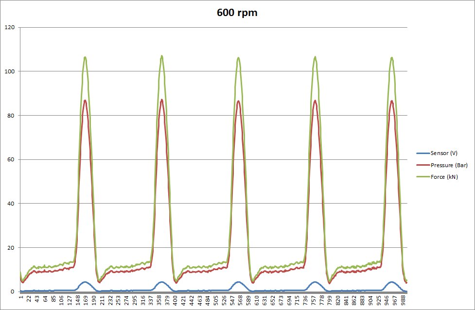
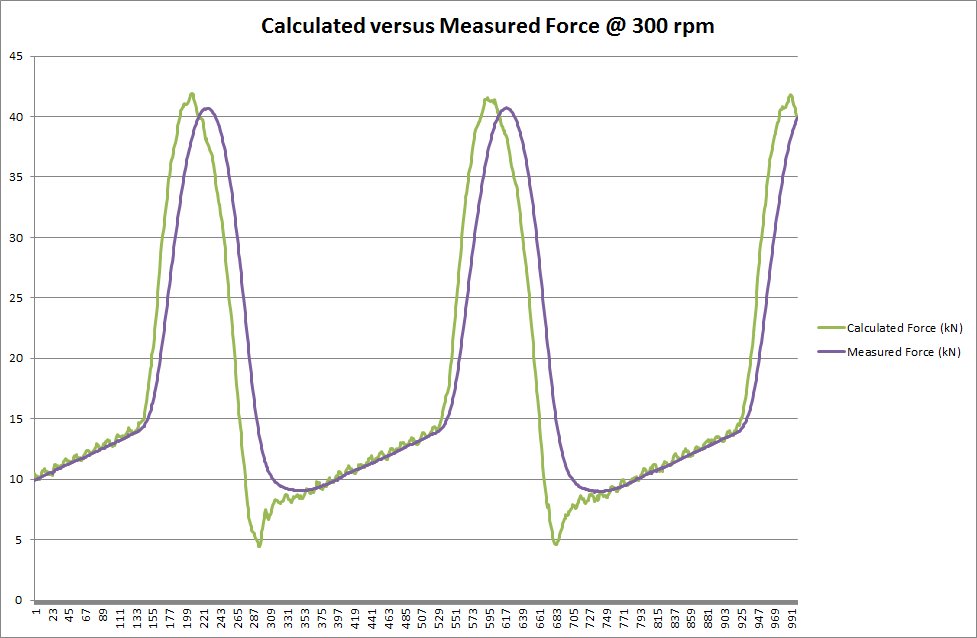
Pressure – Force Verification
It is difficult to find a force transducer with the necessary signal bandwidth and capacity to detect the dynamic force generated at maximum load and pulse frequency, however, tests with a 50 kN strain gauge load cell, with the pulse rate reduced to 5 Hz, to minimise attenuation and phase shift of the force signal, confirms the relationship between measured pressure and resulting force.
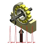
Plain Bearing Tooling
It is very difficult to mount test crankshaft bearing shells as half or partial journal bearings. To avoid the risk of the bearing entry closing, which results in starved lubrication, it is necessary to choose a suitable bearing “pre-load” and “off-set”. It is not obvious how to optimise these values.
Because of this difficulty, tests are run using full journal bearings, with the bearing shells mounted in parts cut from a standard connecting rod, with oil fed under pressure through a hole drilled through the non-loaded side of the connecting rod and bearing shell, thus guaranteeing full film lubrication.
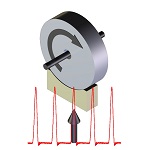
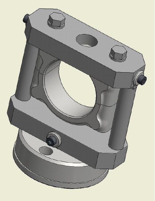
Rolling Element Tooling
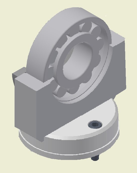
Tooling for rolling element bearings comprises a semi-circular housing supporting the loaded side of the bearing.
Lubrication System
Two lubrication modules are included, one to feed oil to the hydraulic loading system and one to provide lubrication to the test bearing.
-
Technical Specifications Test Shaft Motor: 2.2 kW a.c. vector motor and drive Maximum Motor Speed: 3,000 rpm Cam Drive Motor: 2.2 kW a.c. vector motor and drive Maximum Motor Speed: 1,500 rpm Maximum Dynamic Load: 120 kN Maximum Shaft Diameter – Plain Bearing: 50 mm Maximum Shaft Diameter – Rolling Bearing: 30 mm Maximum Lubricant Supply Rate: 0.725 l/min Maximum Lubricant Supply Temperature: Ambient to 120°C Controlled Parameters Test shaft speed Cam shaft speed Dynamic load (manual) Test fluid temperature Test duration Recorded Parameters Test shaft speed Cam shaft speed Dynamic pressure Lubricant inlet temperature Services Electricity: 220/240 V, single phase, 50/60 Hz, 7.5 kW -
Applications
hydrodynamic lubrication plain bearing fatigue rolling contact fatigue white etching cracks -
Publications
-
User List
Launched 2018
-
Download the Machine Leaflet