-
Description
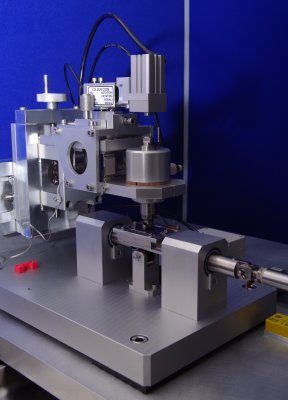
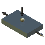
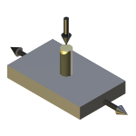
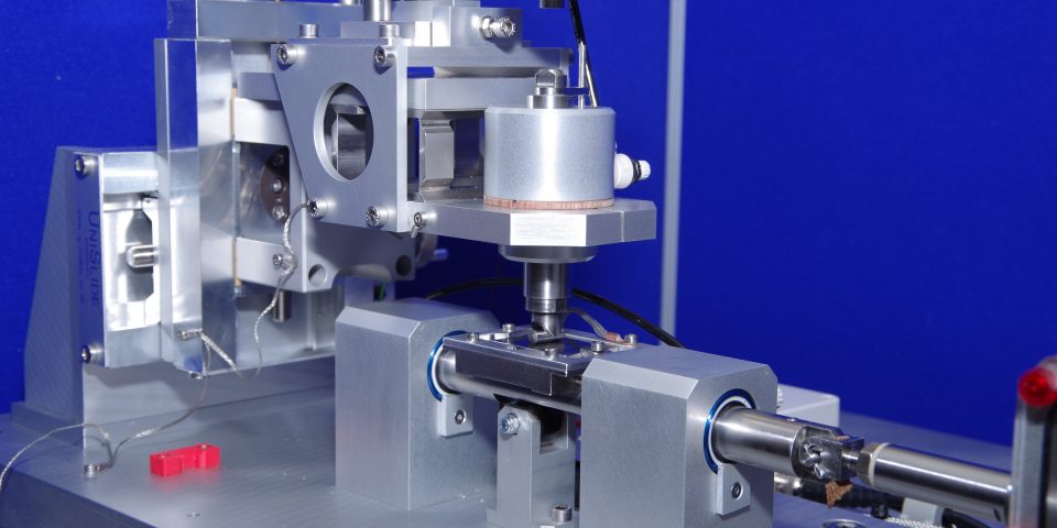
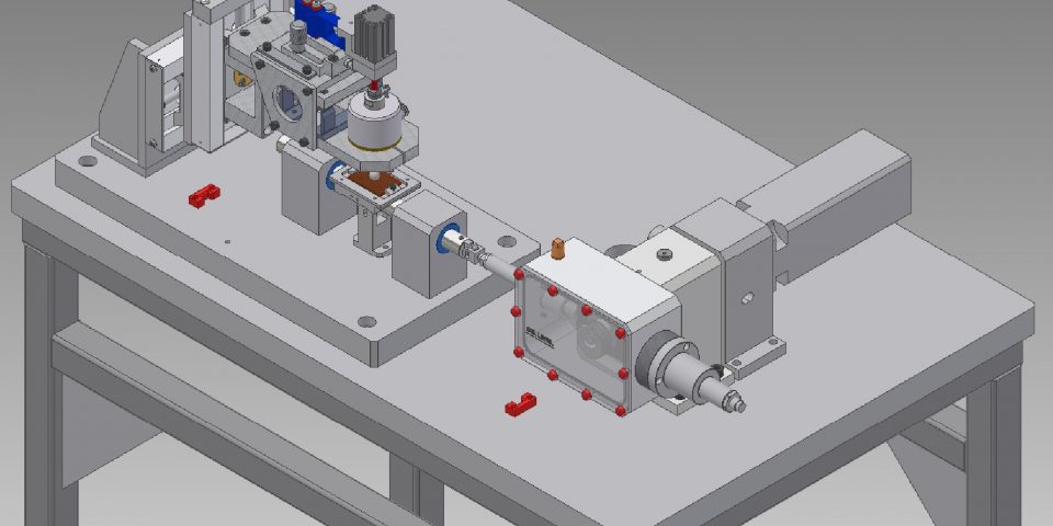
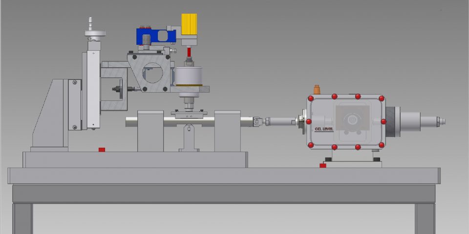
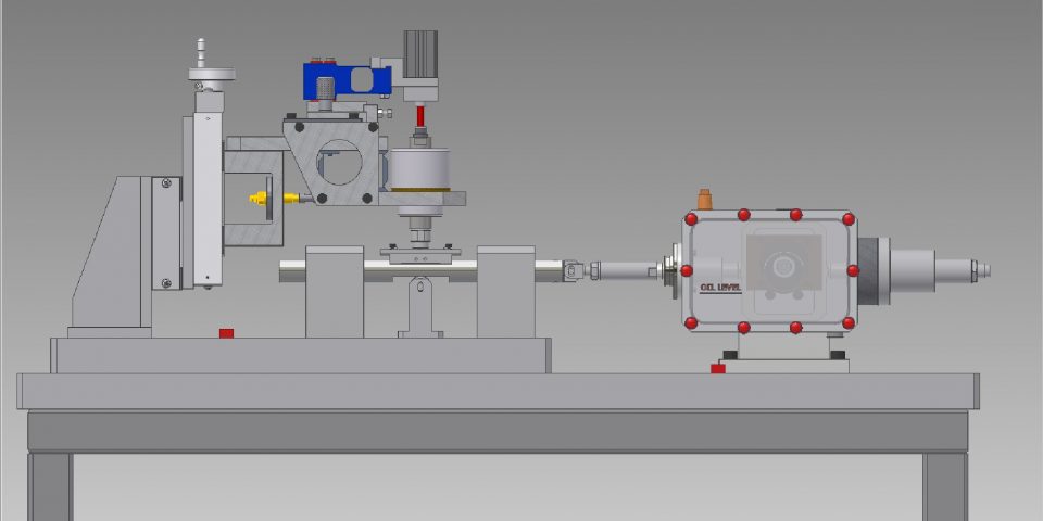
The TE 38 is a long stroke, low load, ball or pin on reciprocating plate rig. It is supplied on its own steel frame, which has been designed to give the machine the correct amount of support to minimize vibration.
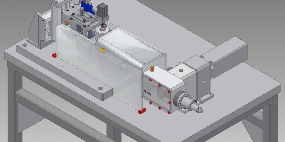
Moving Specimen
The moving plate specimen is carried on a rod, mounted in linear air bearings. A flexible chain provides a conduit for heater and thermocouple cables.
The reciprocating rod is actuated by a scotch yoke mechanism, driven by an a.c. servo motor.
Loading and Friction Measuring System
Load is applied to the fixed specimen carrier by means of an ultra-low friction, servo controlled, pneumatic cylinder.
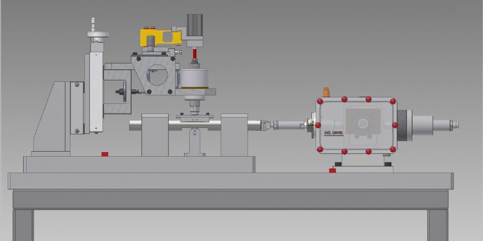
The cylinder is mounted on a strain gauge beam, which provides the load feedback.
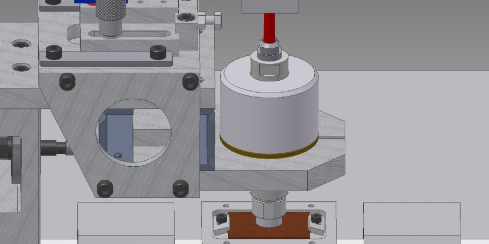
The fixed specimen is mounted at the bottom end of a tubular tool, which is carried in a vertically mounted air bearing. A magnetic coupling connects the top of the tool to the bottom on cylinder rod and holds the specimen out of contact, when no load is applied.
The fixed specimen assembly is mounted on vertical flexures and restrained from horizontal movement by a piezo force transducer.
Mechanical Drive
The mechanical drive consists of an eccentric cam, scotch yoke and plain guide bearings. This converts the eccentric motion of a cam on the drive shaft into horizontal, pure sinusoidal motion of the carrier head. The drive mechanism runs inside an oil bath.
The eccentric cam is driven by a vector controlled variable speed motor with encoder feedback. This ensures that a very stable oscillating frequency is maintained even when friction and temperature conditions change in the contact. The stroke is altered by rotating the position of the eccentric cam with reference to the splined drive shaft.
Operating Envelope
It is necessary to draw a distinction between the mechanical capabilities of the machine (mechanical envelope) and the sensible operating stroke and frequency (measuring envelope) for tests with a given specimen configuration and load. The issue with practical tests is to ensure a suitably low noise to signal ratio. The noise to signal ratio can be assessed by reference to the instantaneous friction signal, where a significant deviation from a square wave may indicate a number of different phenomena:
- Excitation of the force measuring system by machine vibrations.
- Inability of specimens to remain in contact because of the chosen specimen configuration, surface finish and load.
- True tribological effects associated with the presence of a lubricant.
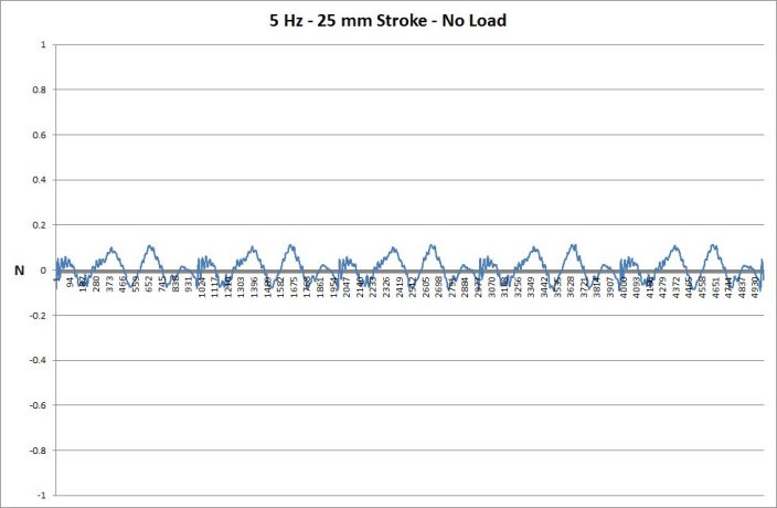
Vibrational excitation can be evaluated at a given stroke and frequency by running the machine with the specimens out of contact.
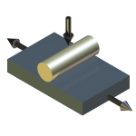
Experimentally, it is always preferable to minimize the noise to signal ratio by maximizing the measured friction. Maximizing the measured friction without imposing unrealistic contact pressures may require the use of contact geometries other than point contact.
Based on point contact experimental data recorded, the recommended operating envelope, at the bottom end of the load range, is as follows:
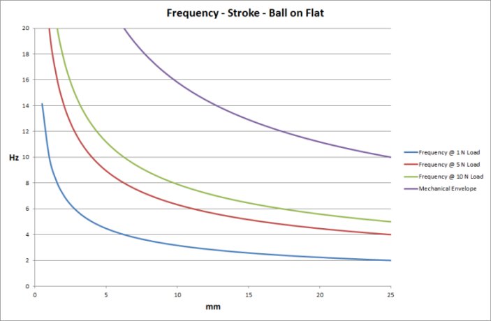
The mechanical envelope indicates the operating range for the machine. In essence, the lower the load, the lower the reciprocating frequency needed to achieve a satisfactory noise to signal ratio. Experiments can be run at any point within this envelope, however, it will be important to evaluate the quality of any friction signal generated, to ensure that an acceptable noise to signal ratio is achieved and to confirm that specimens remain in contact throughout the cycle.
The instantaneous friction, for a half cycle, indicates the frequency and stroke under which acceptable data has been generated, in a sliding point contact experiment. At maximum stroke, a maximum frequency of 8 Hz is acceptable.
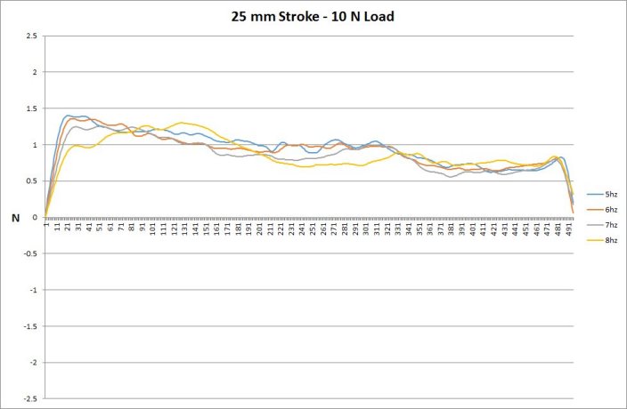
Increasing the load on the specimen will also increase the measured friction and hence improve the signal to noise ratio.
Increasing the frequency to 9 and 10 Hz results in vibrational resonance, rendering the friction measurement meaningless.
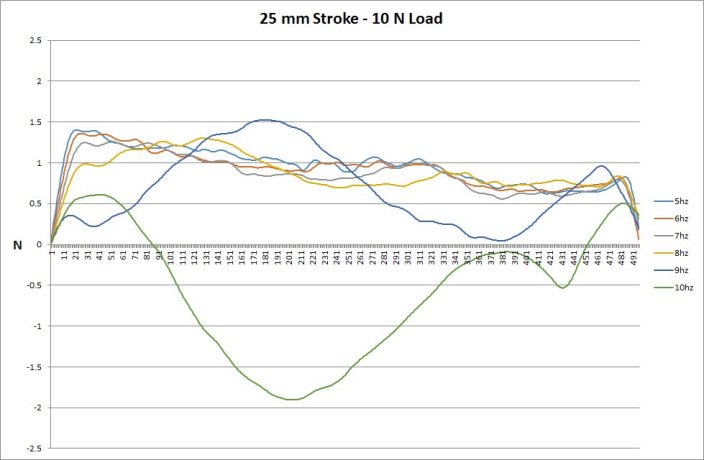
To run at higher frequencies, it is therefore necessary to reduce the reciprocating stroke, to reduce the out of balance forces that drive vibration.
To conclude, when running at a given stroke, load and frequency, it is necessary to review the instantaneous signal generated by the friction force transducer to verify that there is an acceptable noise to signal ratio, noting that it is not possible to establish the noise to signal ratio from the time smoothed, r.m.s. friction force signal.
Friction Force Transducer
During higher frequency (>1Hz) operation, the charge amplifier is operated in the a.c. coupled mode. This eliminates the effects of d.c. drift of the signal over a long time period. The signal is passed through a true r.m.s./d.c. converter amplifier and the final output is the true mean force sensed. The instantaneous friction signal is also recorded, in bursts, via the high speed data acquisition interface.
For low frequency sliding (<1Hz), stick slip, single pass sliding and also for calibration of the transducer, the charge amplifier is operated d.c. coupled, in quasi-static mode. This gives signal decay times up to 100,000s, sufficiently long when compared to typical measurement time scales for the zero not to have moved significantly during the measurement. The Time Constant TC is set to [LONG].
Contact Resistance Measurement
The moving specimen carrier head is electrically isolated from the drive shaft and therefore from the fixed specimen. This allows a millivolt potential to be applied across the contact from a Lunn-Furey Electrical Contact Resistance Circuit.
Variations in this voltage are indicative of the level of metallic contact, provided that both test specimens are conductors of electricity. This measurement is valuable for observing the formation of chemical films from anti-wear and extreme pressure lubricants, the breakdown of non-conducting layers and coatings or the build-up of oxides.
Temperature Control and Measurement
In the TE 38 the temperature is measured with a k-type thermocouple pressed against the lower plate specimen. This is a good measure of the actual contact temperature because temperatures due to frictional heating are small.
Temperature control is by software PID with set point ramps and dwells programmed in the COMPEND Test Sequence File software.
Magneto Inductive Sensor
This provides positional feedback for the moving specimen and is best used in conjunction with the high speed interface to allow force-displacement data to be generated. The sensor is mounted on the back of the reciprocating assembly.
Control and Data Acquisition
The TE 38 has PC based sequence control and data acquisition features. This is provided by an integrated SLIM 2000 Serial Link Interface Module and COMPEND 2000 software running on a host PC.
-
Technical Specifications
Load Range: 1 to 50 N Frequency: 0.5 to 20 Hz Max Frequency/Max Stroke: 8 Hz at 25 mm 20 Hz at 4 mm stroke Temperature: Ambient to 150ºC Stroke Range: 0. to 12.5 mm (10 steps) 12.5 to 25 mm (10 steps) 0. to 12.5 mm (continuously variable) Contact Potential: 50 mV dc signal Friction Transducer: Piezo-Electric Type Interface: Serial Link Interface Module Software: COMPEND 2000 Motor: 0.48 kW ac servo motor Automatically Controlled Parameters Frequency Load Temperature Test Duration Manually Controlled Parameters Stroke Measured Parameters Frequency Load Friction Force Stroke Position Temperature Electrical Contact Resistance Services Electricity: 220/240 V, single phase, 50/60 Hz, 3.2 kW Clean, dry air: 0.4 cubic metres per minute at 8 bar -
Applications
delamination wear elastomeric polymers pin on plate plastic sheet rubber materials scuffing soft materials static friction stick-slip Stribeck curve -
Publications
-
User List
Launched 2011
SINTEF Norway Rolex SA Switzerland -
Download the Machine Leaflet