-
Description
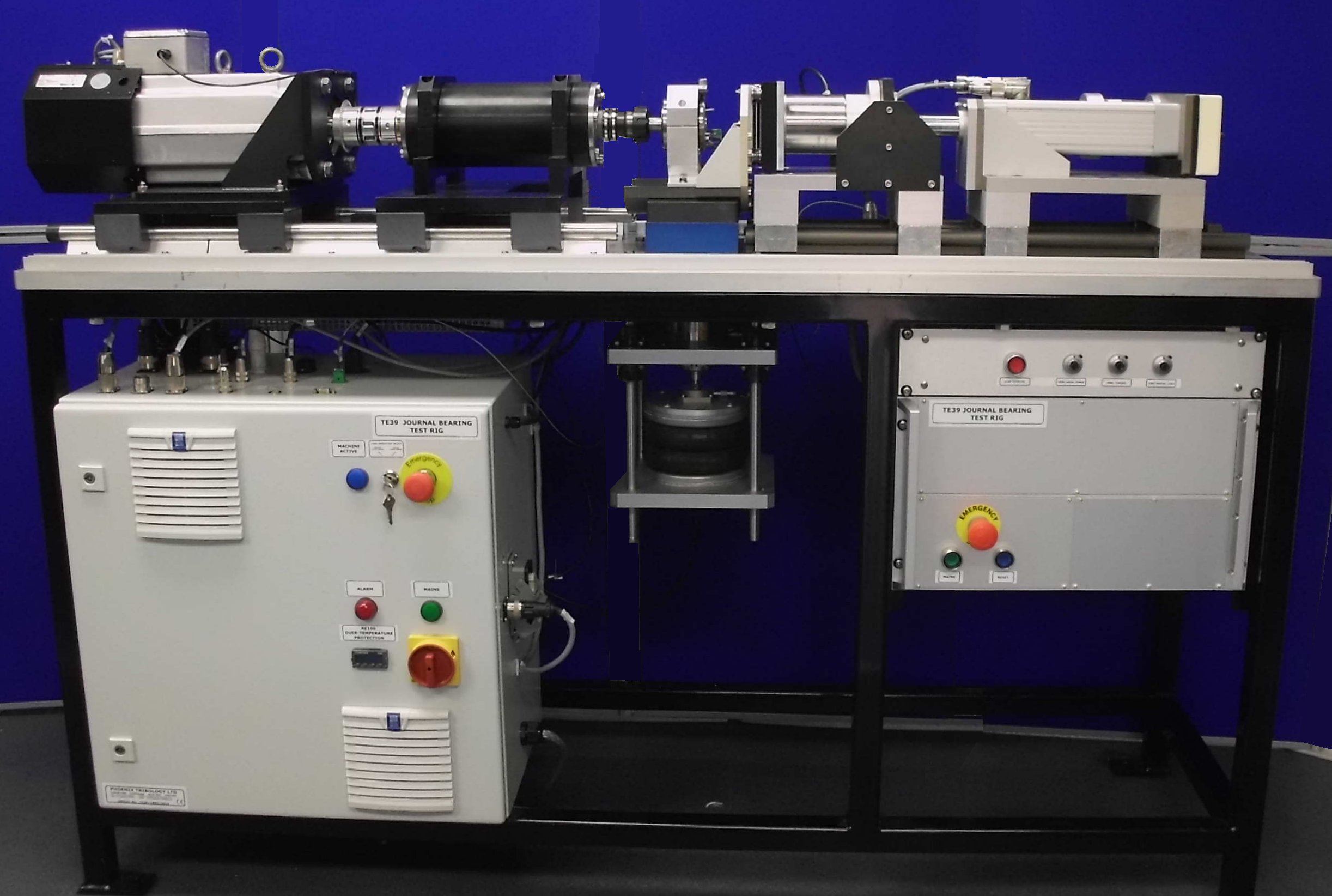
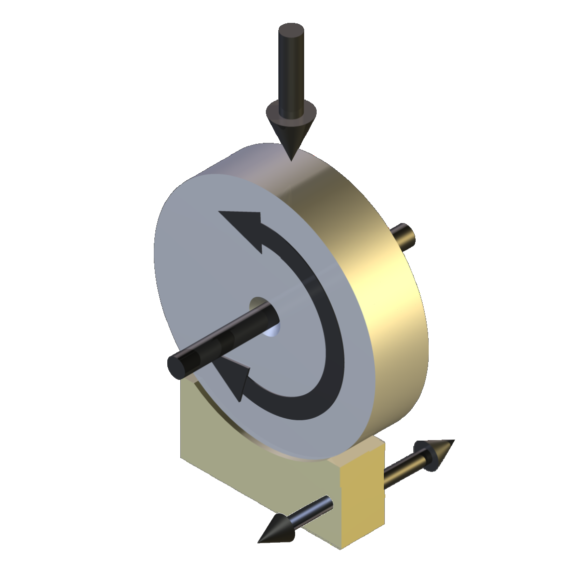
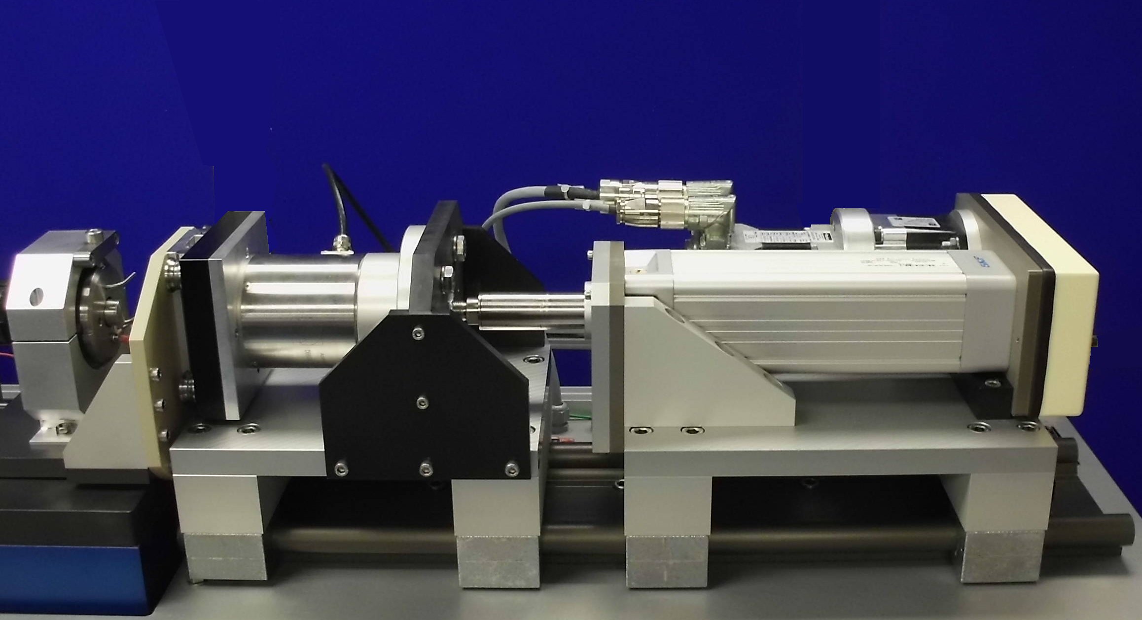
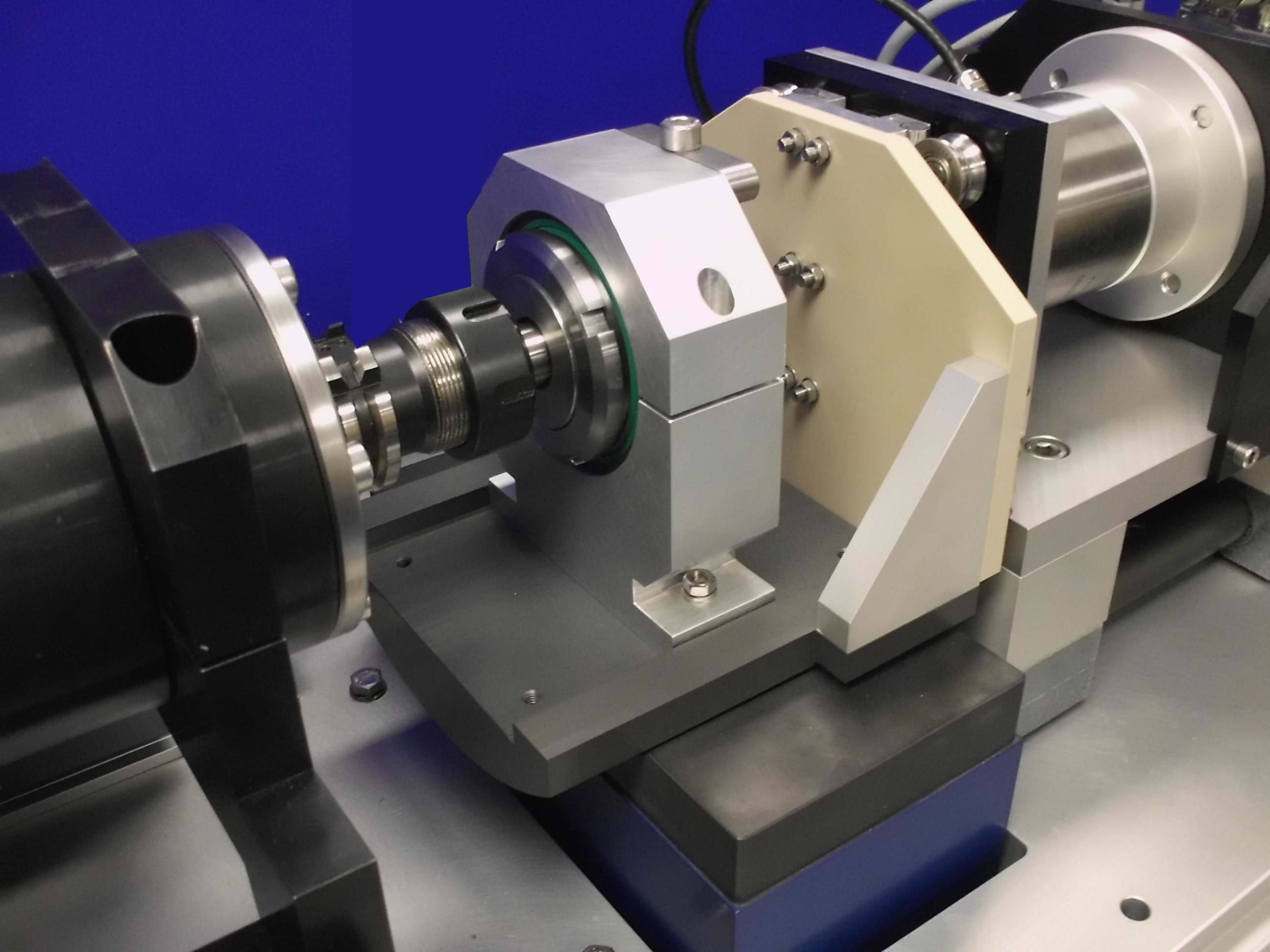
The rig is constructed with similar geometry to a conventional lathe, comprising a “head-stock”, for carrying shaft samples, a “tail-stock”, mounting a combined axial force and radial torque transducer, and a “tool-post”, for mounting a specimen and applying a radial force.
The head-stock and tail-stock assemblies are mounted on standard linear slide, on bearing blocks, with manual clamps.Head-stock
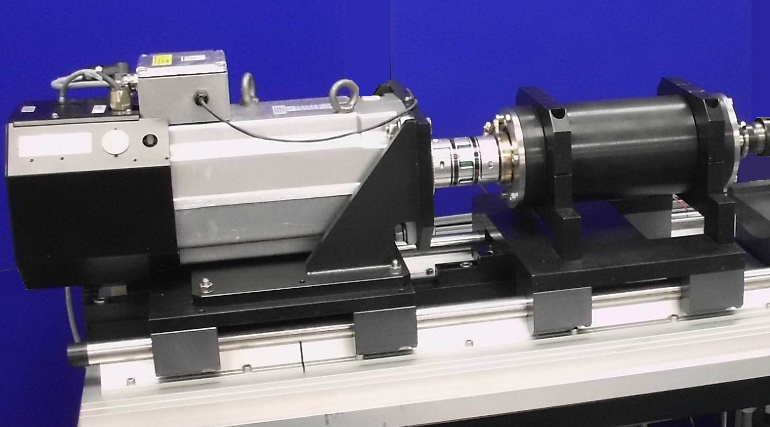
The head-stock arrangement comprises an interchangeable motor and a spindle assembly, each mounted on separate bearing slides. The location of both is fixed during normal operation.
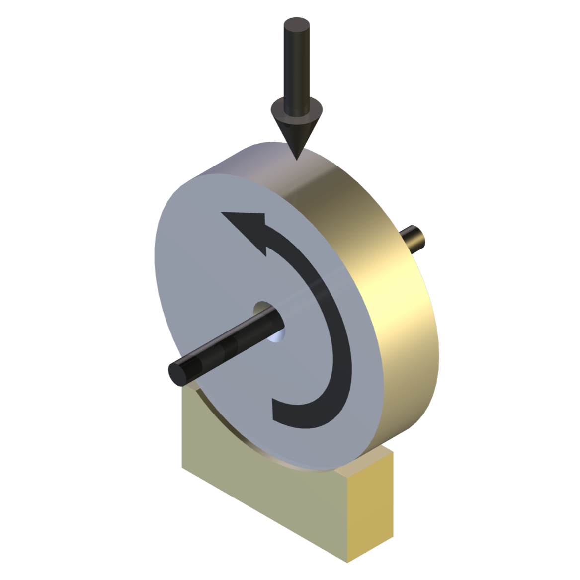
For continuous rotation at speeds up to 2000 rpm, a servo motor is connected directly to the spindle assembly.
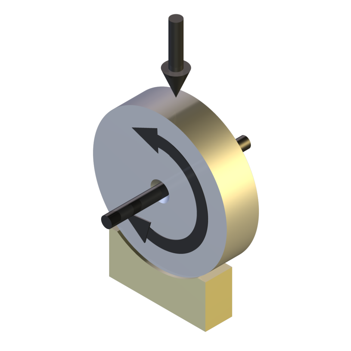
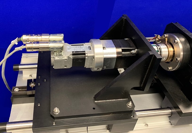
For oscillating motion of +/-20° at 1 Hz, the direct drive motor is replaced with a smaller servo motor driving through a 100:1 reduction gear-box.
The spindle assembly is designed to accommodate specimen shafts with a diameter ranging from 5 mm to 30 mm and incorporates a pull-in taper. For smaller diameter specimens, operating at lighter loads, a standard machine tool taper collet is used. For larger diameters, and higher loads, taper and shaft specimens are manufactured as a solid part.Tail-stock
The tail-stock comprises a linear slide mounted bracket, supporting a horizontally mounted, non-rotating, combined axial force and torque transducer. The only forces acting on the assembly is the axial force and a pure couple generated by the friction in the test bearing.
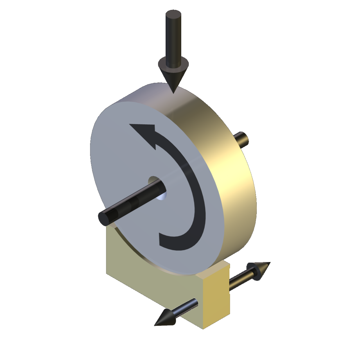
In order to produce reciprocating axial motion, the tail-stock is free to slide on linear bearings, with motion and position controlled by a coaxially mounted ball-screw actuator, giving a maximum stroke of 30 mm at a maximum frequency of 1 Hz.
Loading System
The “tool-post” is mounted on a linear slide connected to the tail-stock, so that both move together. It comprises a standard air bellows, air bushing and cross-head assembly, with either a 2.5 inch or a 6 inch pneumatic bellows for load application, depending on required load range.
A force transducer is included for measurement and feedback of load, for servo pneumatic control.
A concave radial air bearing is mounted on the cross-head assembly, with a 25 mm ball as the self-aligning interface between the air bearing and cross-head.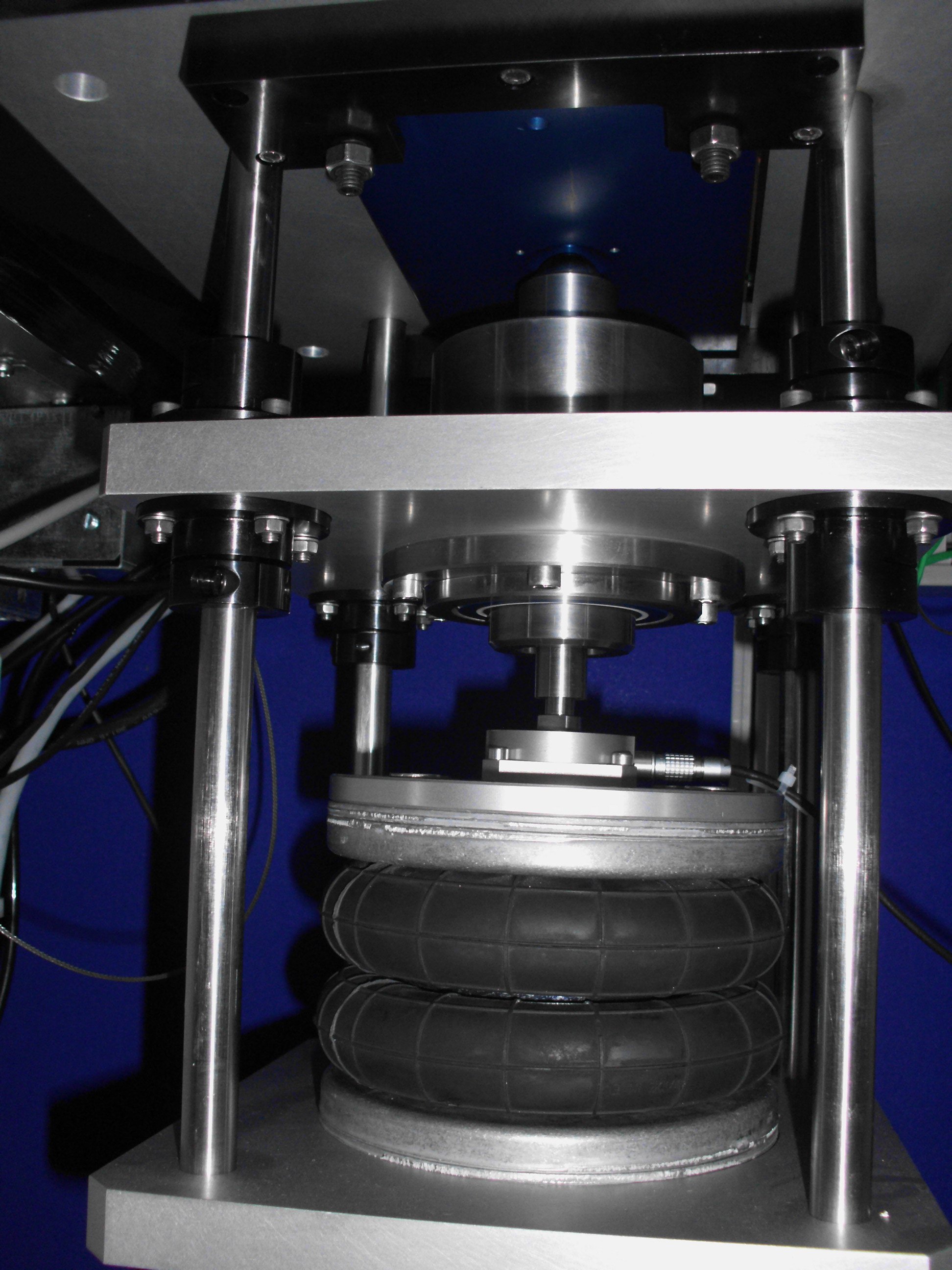
The air bearing supports the journal bearing specimen tooling, the basic form of which is a 250 mm diameter cylinder, machined down to provide tooling locations for holding both full and partial journal bearing samples.
By connecting the loading system slide to the torque transducer slide, both can be indexed together to provide the required axial motion of 30 mm, with the journal bearing specimen tooling sliding relative to the air bearing.Transducer Connection
The journal bearing specimen tooling is restrained from rotation by connection to the axial force and torque transducer, through a vertically mounted linear guide. This allows vertical movement of the specimen tooling relative to the transducer, without interfering with load application or applying a bending moment to the end of the transducer.
 Bearing Specimen Alignment
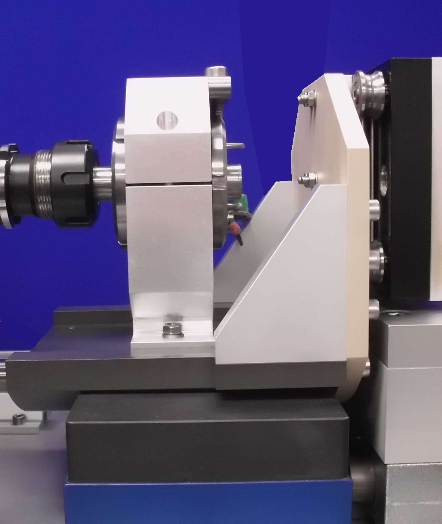
In order to ensure that the test bearing and shaft are axially aligned the test bearing is mounted a spherical plain bearing housing. The lateral position of the housing provides adjustment for lateral misalignment.
Instrumentation and Control
Control and data acquisition are implemented via host PC running COMPEND 2020 Windows compatible software, in conjunction with a Phoenix Tribology USB micro-controller interface.
Automatic control is implemented via user programmable test sequences. Manual control is implemented using on screen toggles. Data is stored to hard disc in either .csv or .tsv file formats. -
Technical Specifications
Maximum Radial Load: 5 kN Bearing/Shaft Diameter: 5 to 30 mm Spindle Taper: DIN 69871A, taper ISO 50 Rotary Motion: Speed: 0 to 2000 rpm Continuous Torque: 56.4 Nm Peak Torque: 136 Nm Oscillating Motion: Amplitude: Variable 0 to +/-20° Frequency: 0.001 to 1 Hz Axial Motion: Maximum Thrust: 5 kN Stroke: 0 to 30 mm Frequency: 0.001 to 1 Hz Air Bearing: Input Pressure 0.41 MPa Ideal Load at 5um Fly Height 6672 N Stiffness 1009 N/μm Flow 4.96 NLPM Fly Height 5 microns Porous Media Material Carbon Viable Pressure Range 0.414 – 0.552 MPa Maximum Allowable Pressure Supply 0.689 MPa Common Guide Surfaces Hard-coated aluminium Guide Surface Finish 16 RMS Controlled Parameters Frequency (rotational, oscillatory, reciprocating) Amplitude (oscillatory, reciprocating) Test Duration Load Measured Parameters Frequency Amplitude Load Friction Torque Axial Friction Force RMS Friction Contact Potential Services Electricity: 380/415V, three phase plus neutral, 50/60 Hz, 20 kW Air: 4 cfm at 8 bar (120 psi) -
Overview Videos
-
Index Tags
-
Download the Machine Leaflet

Call us on +44 (0) 1635 298279
Email : info@phoenix-tribology.com
Email : info@phoenix-tribology.com