
Background
The US Auto/Steel Partnership 2011 report “Impact Sliding Wear Tests on Duplex-Treated Die Materials” describes an impact sliding rig developed by the University of Windsor, Ontario, in which a pneumatic actuator is used to drive a ball against an inclined sample plate, mounted at an angle on a pivot arm and pre-loaded against a stop, by a compression spring. The ball impacts the plate, which deflects through a pre-set angle, causing a wear track to be formed.
Description
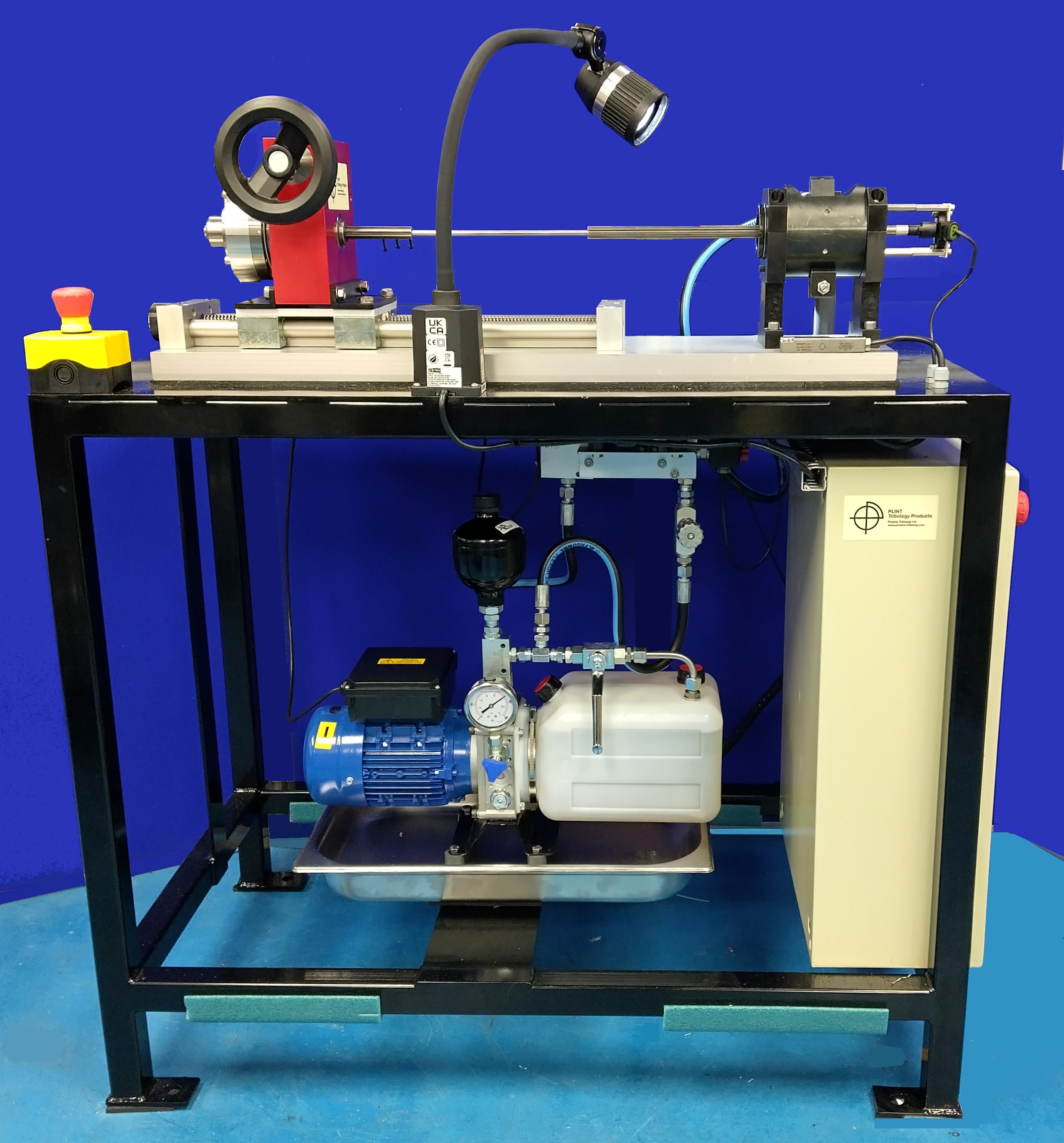
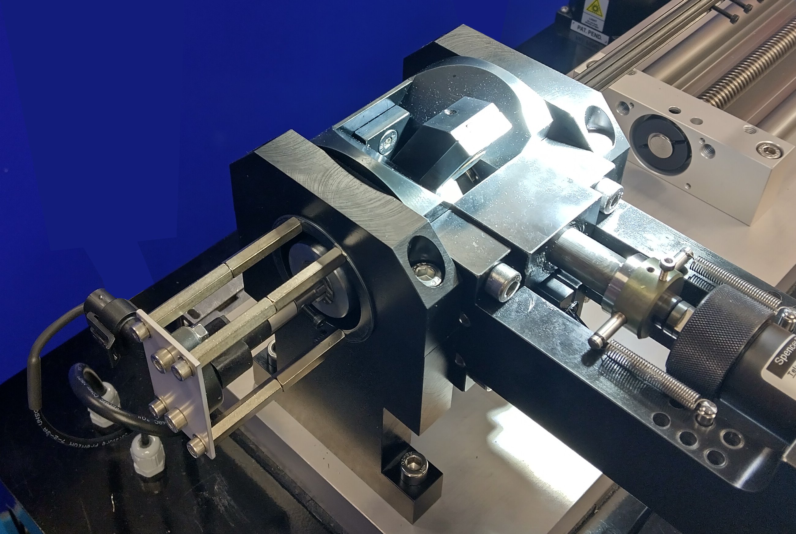
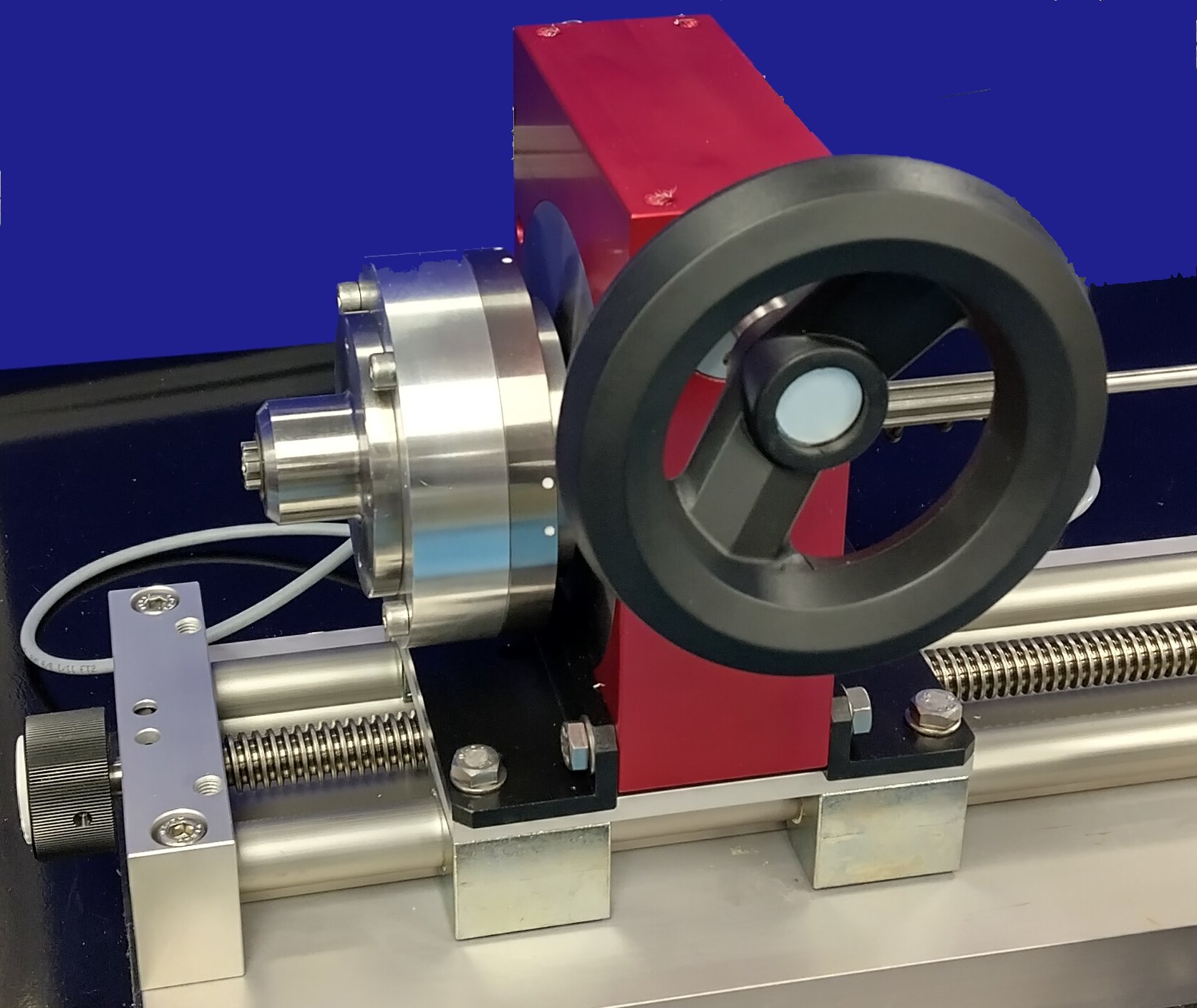
With the TE 43 Impact Test Rig, a torsion bar is used to generate the resisting force. The spring rate of the torsion bar is varied by adjusting its effective length, by varying the clamping position. The torsion bar is connected to a torque transducer, allowing the impact forces to be sensed. A manually adjusted worm gear-box is used for winding torque into the torsion bar and a linear slide is provided for adjusting the effective length.
The impact motion is generated by a small hydraulic cylinder of the type used in punching applications. The associated hydraulic controls allow adjustment of the impact velocity.
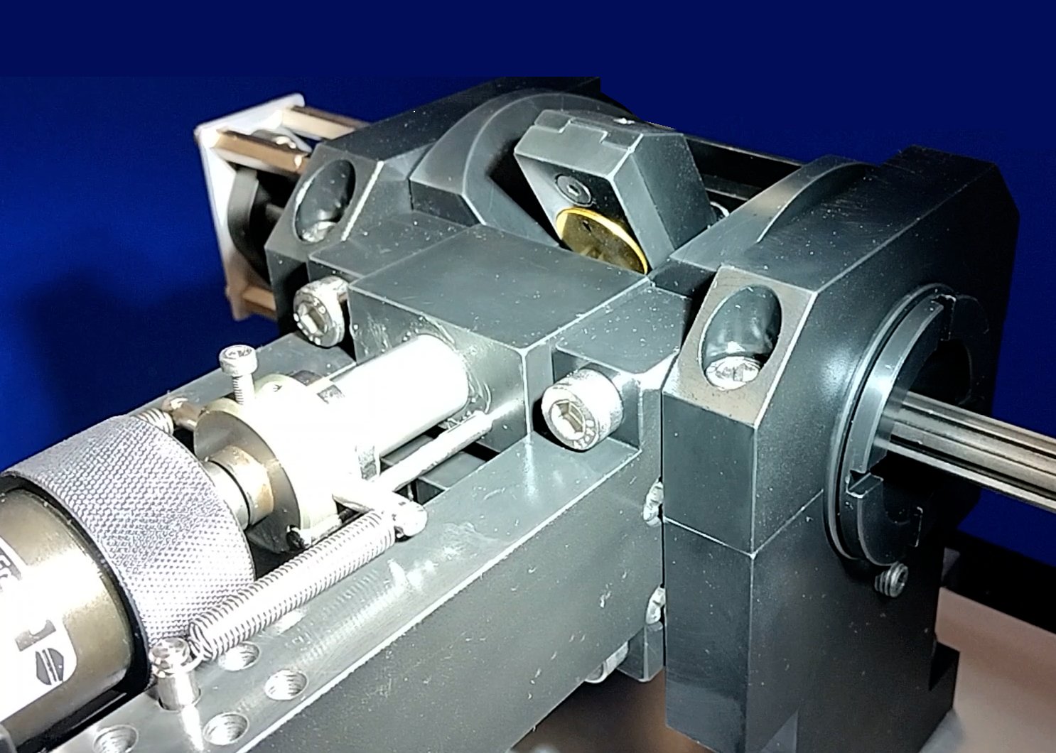
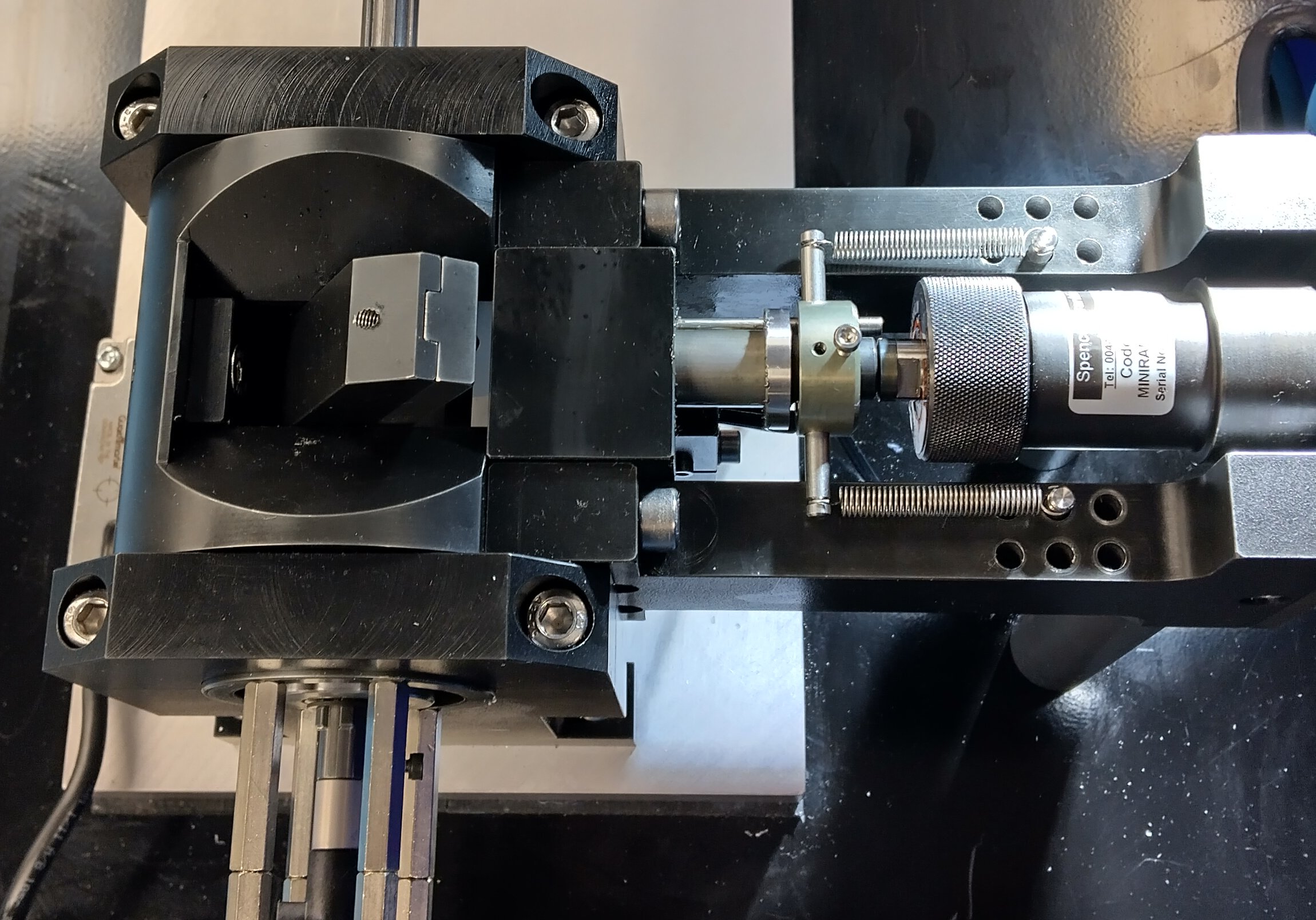
The test sample is pre-loaded against a stop, at an angle of 30 degrees to the horizontal. The cylinder stroke length, which governs the amount of rotation of the pivot arm, after impact, is also set with a mechanical stop.
The length of the wear scar generated depends on the amount of rotation produced. With the geometry of this machine, a rotation of approximately 6.5 degrees generates a wear scar of approximately 2.5 mm. The maximum practical scar length is 4 mm.
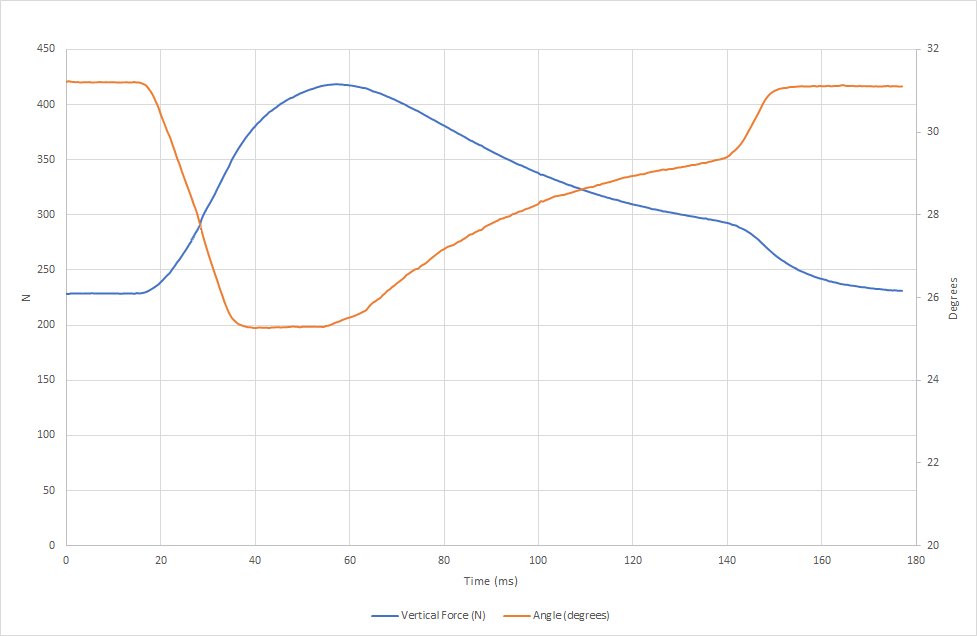
As the pivot arm rotates, after initial impact, the resisting force increases. The rotation of the specimen is sensed with an encoder and the torque on the torsion bar measured.
An inbuilt USB endoscope allows the wear scar to be observed, either continuously, or with periodic image capture, allowing analysis of the morphology of the contact, as impacts are accumulated.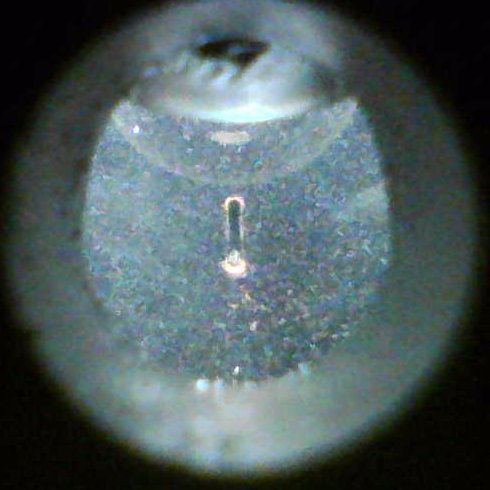 In situ endoscope image
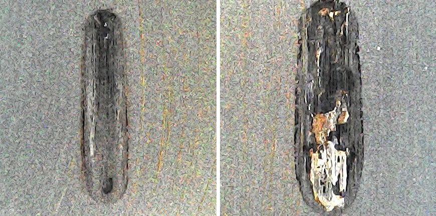 Post-test wear scar images at 1500 and 3000 impacts
-
Technical Specifications
Load Range: 0 to 2000 N Load Rise: Pre-load plus 100% Minimum Impact Period: 0.1 seconds Wear Track Length: 2 – 4 mm (adjustable) Rotation Angle: 6.0 to 7.5 degrees Interface: High Speed Data Acquisition Card Software: COMPEND 2000 Manually Adjusted Parameters Torsional Spring Rate: By adjusting torsion rod length Pre-load: By rotating transducer Total Impact Displacement: By setting actuator mechanical stop Impact Velocity: By adjusting flow control valve Controlled Parameters Actuator Impact Trigger: Solenoid valve Actuator Withdrawal: Solenoid valve Image Capture: USB endoscope Measured Parameters Torque: Transducer Pivot Rotation: Encoder Services Electricity: 220/240V, single phase plus neutral, 50/60 Hz, 2 kW -
Overview Videos
Machine Overview
-
Index Tags
adhesive delamination ball on flat impact sliding coatings delamination wear forging forming forming lubricants friction & wear tests impact impact sliding tool and die wear traction curve -
Download the Machine Leaflet

Call us on +44 (0) 1635 298279
Email : info@phoenix-tribology.com
Email : info@phoenix-tribology.com