-
Description
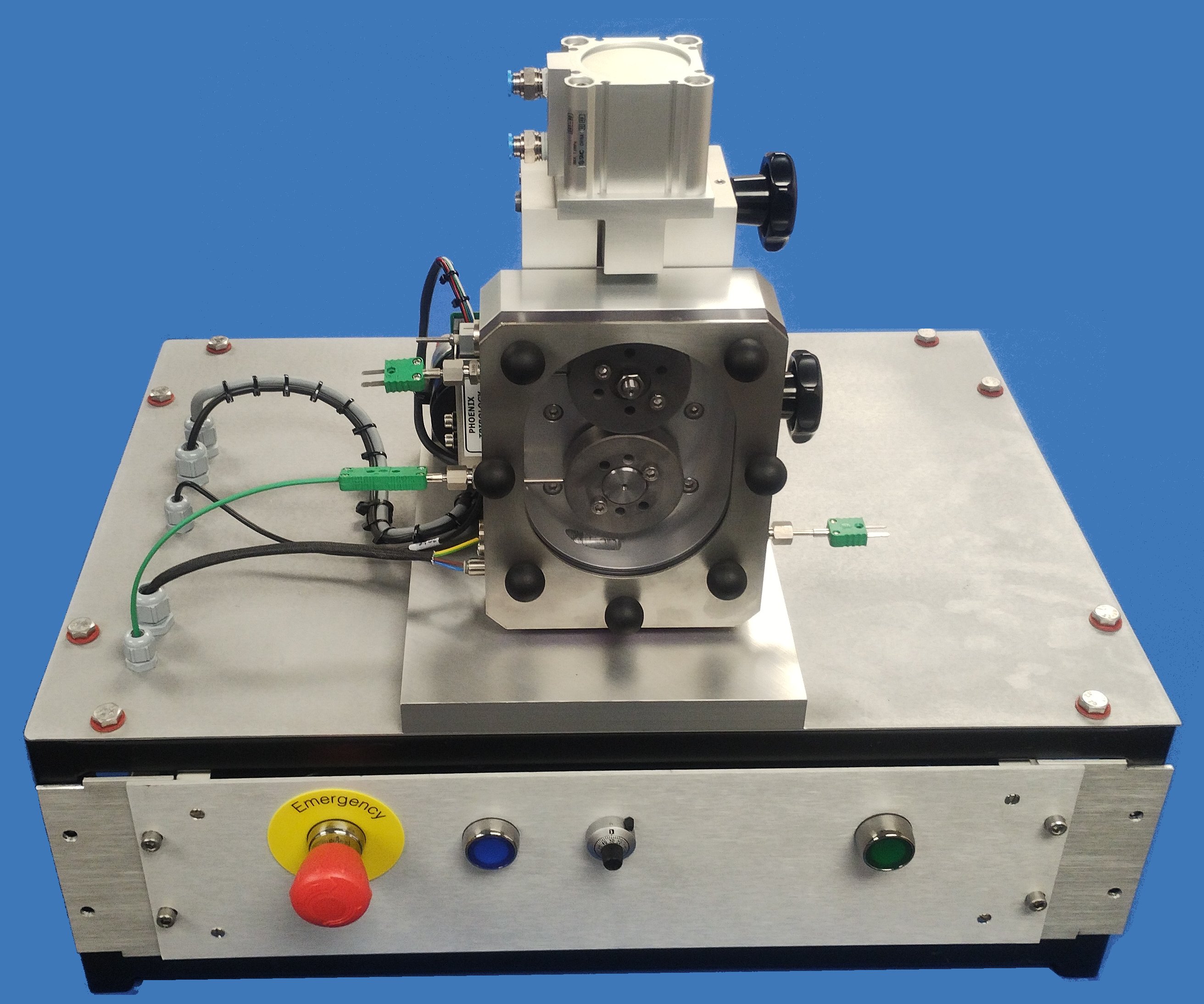
A bearing housing carries two parallel shafts. The lower shaft carries a flat profile ring or roller and is connected to a d.c. servo motor. The upper shaft is carried in a spherical bearing at one end that permits rotation about the gear contact line and has a floating bearing at the other end. This allows the shaft to pivot freely in the vertical and horizontal axes.
Horizontal movement in the direction perpendicular to the upper shaft axis and is resisted by a strain gauge transducer. This gives measurements of the tangential force in the contact, which is displayed as friction force on the control unit.
Load is applied by applied by low friction pneumatic cylinder, which is manually set using a precision regulator, pressing on the outer race of the floating bearing. A pressure transducer is provided to sense the applied load.
A sealed chamber surrounds the test specimens and incorporates a heater element to maintain the test fluid temperature.
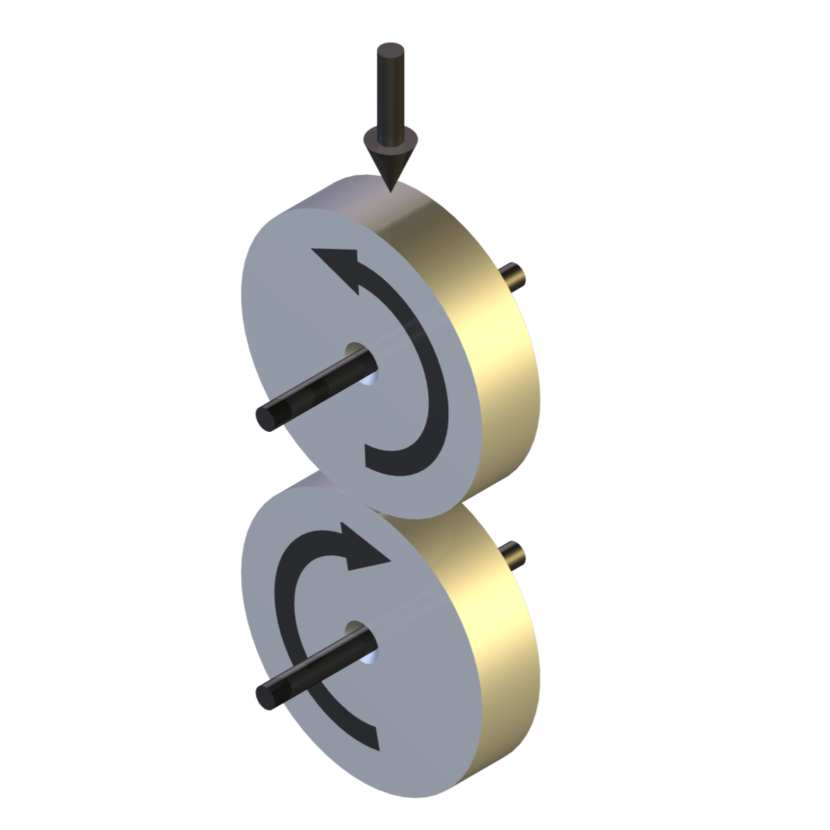
In two roller configuration the upper shaft carries a roller and is driven from the lower shaft through a pair of gears. Six fixed percentage slip ratios are provided. The upper roller is mounted on a self-aligning bearing to achieve full width line contact between the specimens.

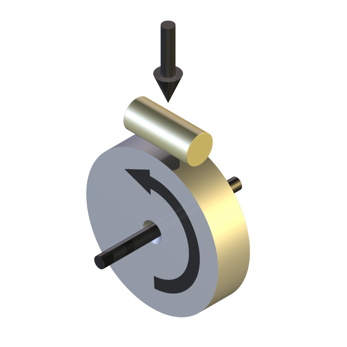
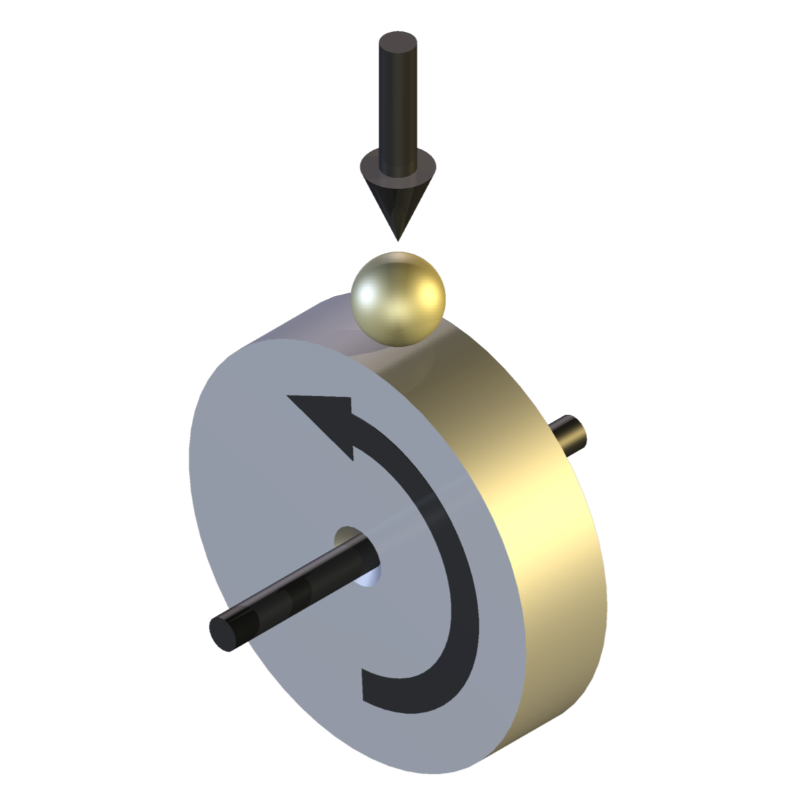
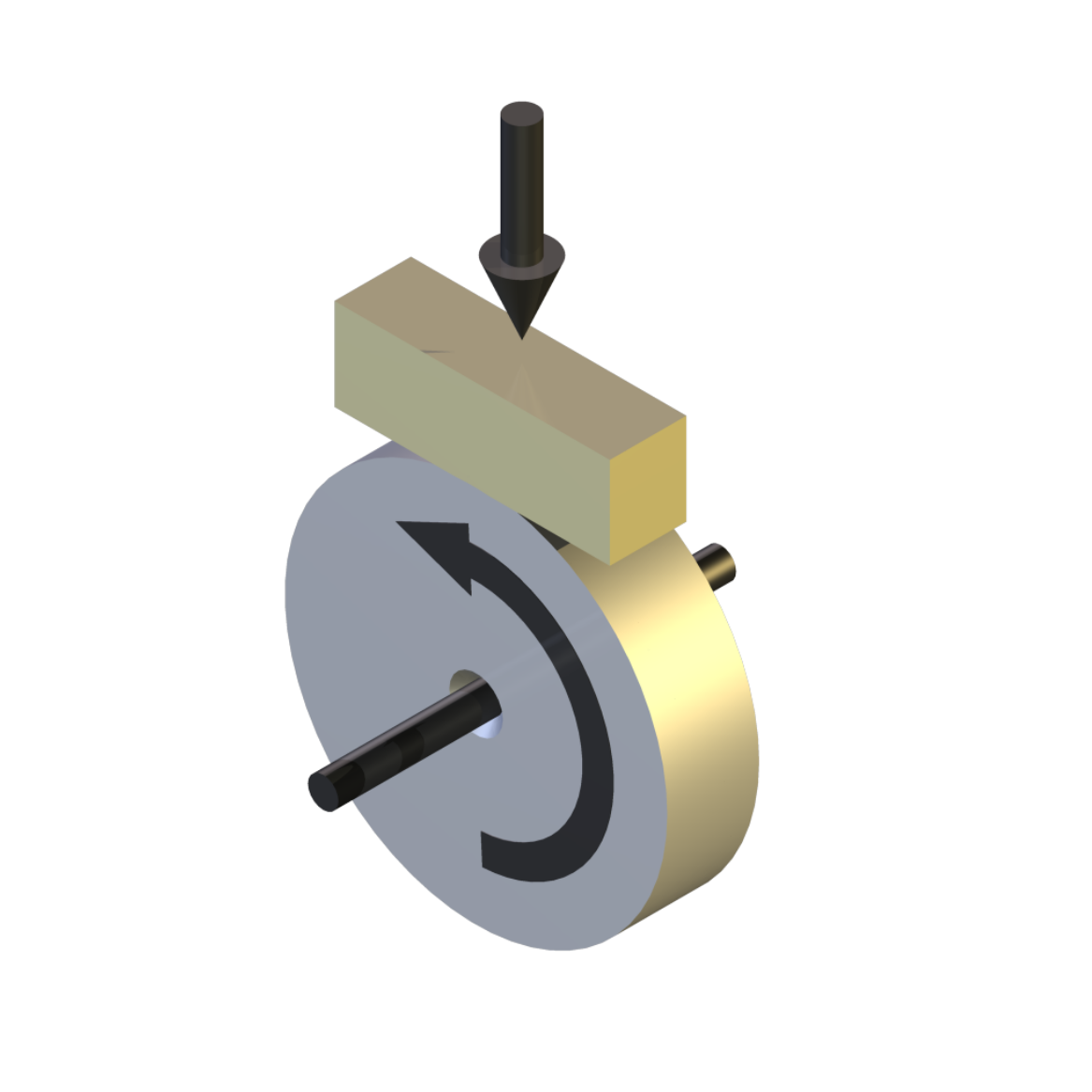
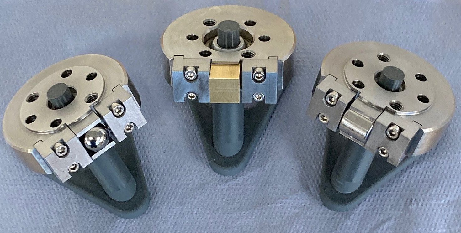
In block on ring configuration the upper shaft carries a holder for the fixed specimen and is restrained from rotating. The specimen may be a ball (ball on cylinder test), a block (block on ring test) or a cylinder (crossed cylinder test). A holder for blocks described in ASTM G77 test is included.
Roller and block specimens can be manufactured easily from a variety of materials including metals, plastics, elastomers and ceramics.
Control and Data Acquisition
Control and data acquisition are implemented via host PC running COMPEND Windows compatible software, in conjunction with a Phoenix Tribology USB micro-controller interface.
Automatic control is implemented via user programmable test sequences. Manual control is implemented using on screen toggles. Data is stored to hard disc in either .csv or .tsv file formats. -
Technical Specifications
Contact Geometry: Crossed Cylinder Ball on Cylinder Block on Ring Two Roller Shaft Centre Distance: 60 mm Roller Size: 60 mm diameter Sliding Specimen: 12.7 mm ball, roller or block Speed Range: 30 to 850 rpm Equivalent Velocity: up to 4.7 m/s Slide-Roll Ratio Gears: 0.00%, 3.33%, 5.00%, 10.00%, 15.00% & 20.00% Friction Range: 130 N Friction Measurement: Databeam (strain gauge transducer) Load Range: 50 to 750 N Load Actuator: Pneumatic cylinder Load Control: Precision pressure regulator Load Measurement: Pressure transducer Bath Temperature: ambient to 150°C Heater Power: 150 W Temperature Sensor: k-type thermocouple Interface: USB Serial Link Interface Module Software: COMPEND 2000 Motor: Brushless d.c. servo motor – 200 W Automatically Controlled Parameters Rotational Speed Reservoir Temperature Test Duration Manually Controlled Parameters Load Measured Parameters Rotational Speed Load Friction Force Temperature Number of Revolutions Test Duration Sliding Speed Friction Coefficient Sliding Distance Services Electricity: 220/240V, single phase, 50 Hz, 1.2 kW 110/120 V, single phase, 60 Hz, 1.2 kW -
Training & Promotional Video
-
Index Tags
-
Download the Machine Leaflet

Call us on +44 (0) 1635 298279
Email : info@phoenix-tribology.com
Email : info@phoenix-tribology.com