-
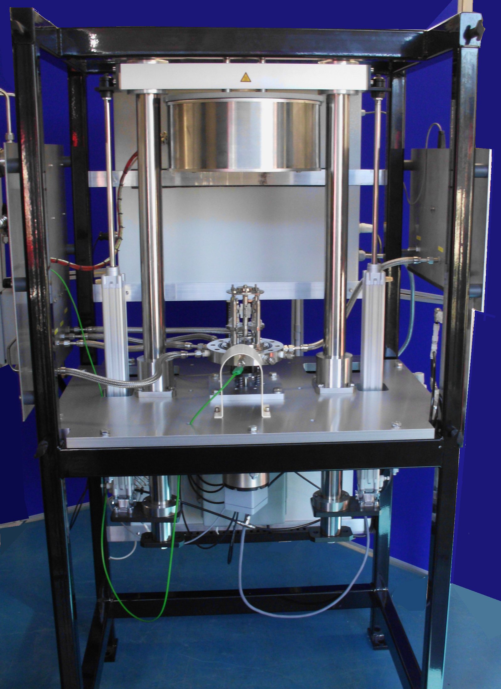
Description
The rig incorporates a simple, two-part, miniature autoclave, comprising a base plate and an upper body, mounted on a voice coil actuator. Specimen tooling and pipe connections are mounted on the base plate, leaving the upper body free to be removed, allowing the system to be set up and tested open.
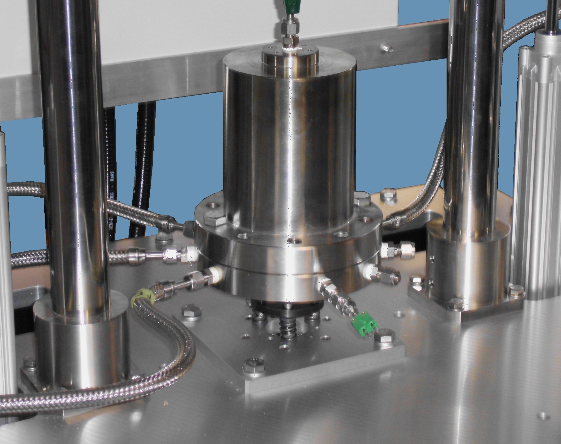
Autoclave lid fitted The complete assembly is vibrated about a vertical axis, inducing relative motion between two sets of moving and fixed specimen carriers. A non-contact displacement measurement sensor is provided for sensing the relative motion.
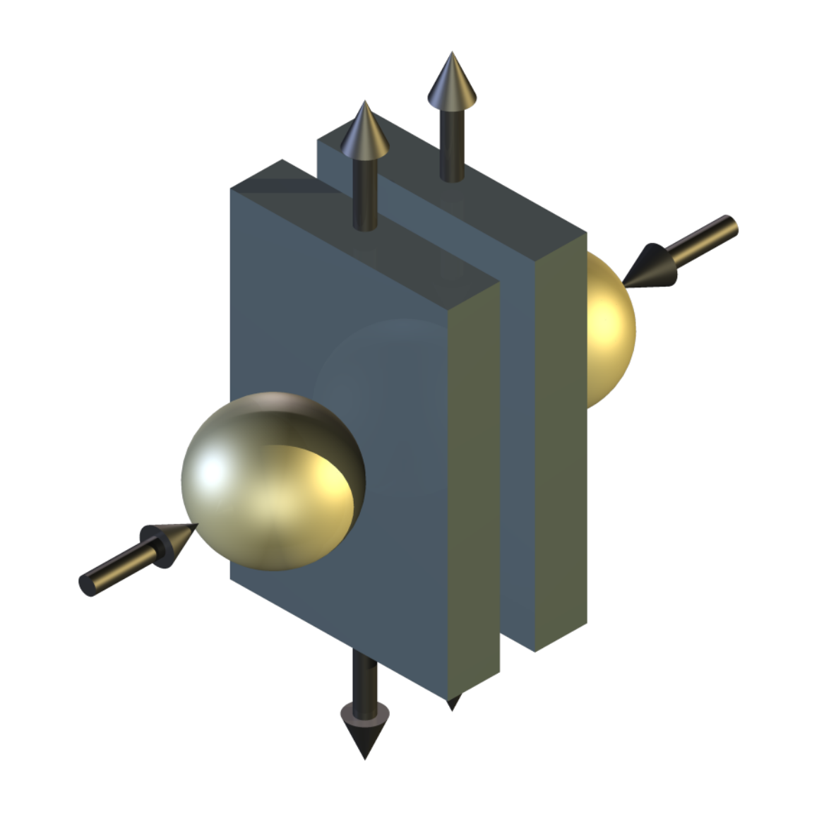
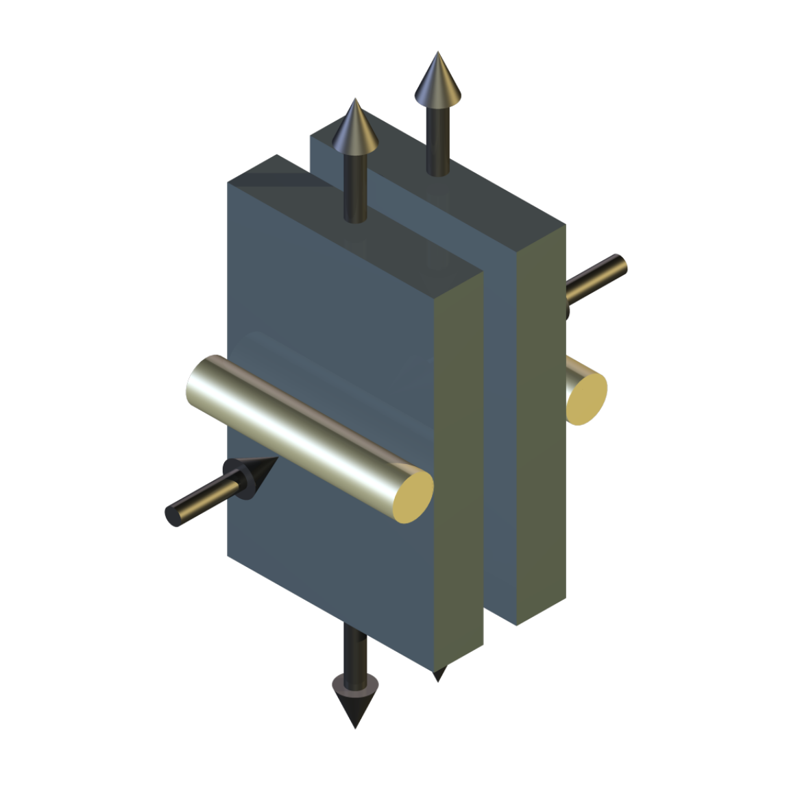
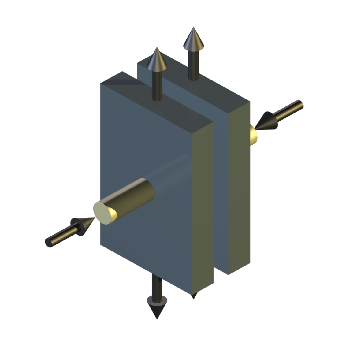
The fixed specimens are mounted on lever arms and are loaded against moving specimens by a stainless steel spring, tensioned between the levers.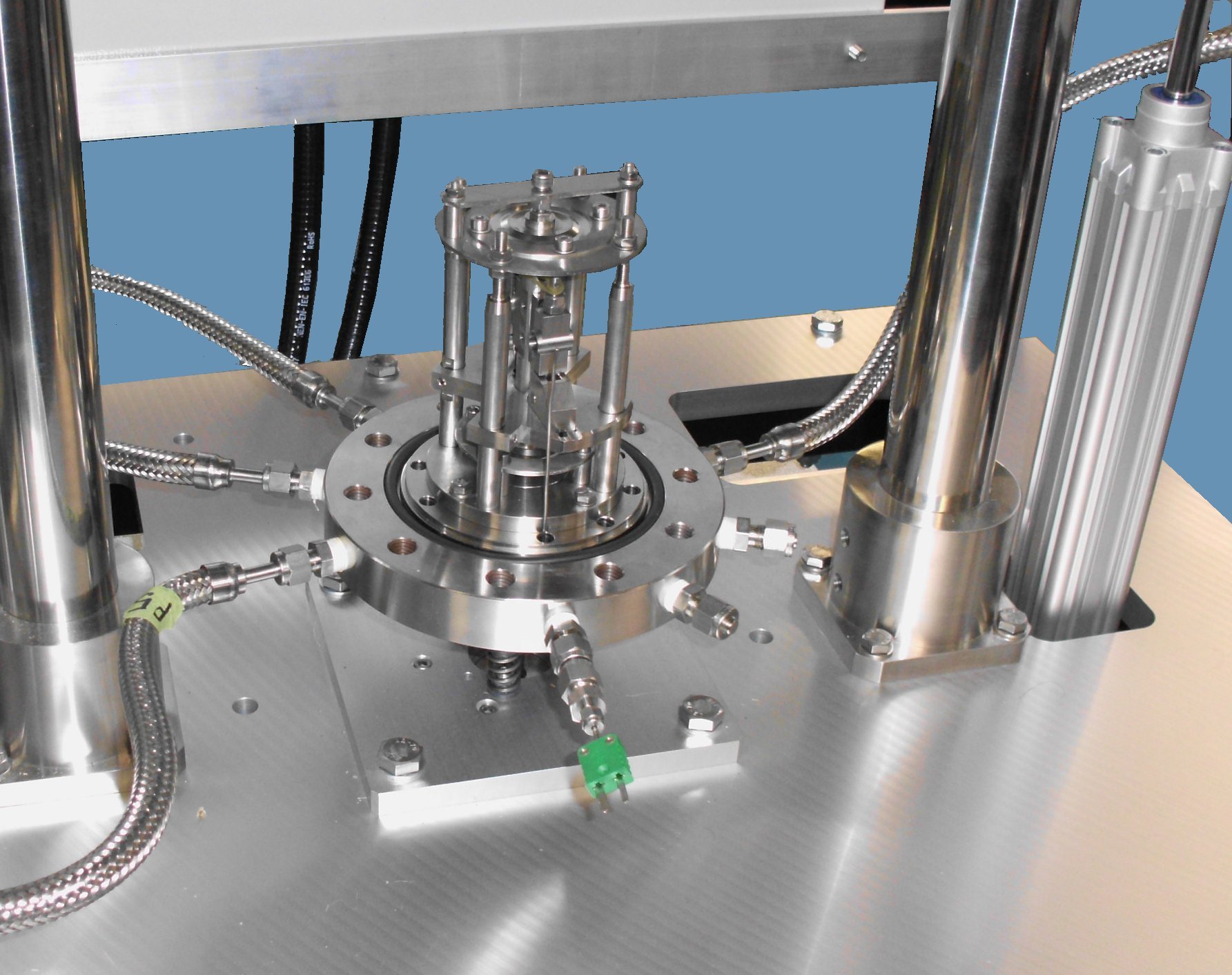
Fretting test assembly The moving specimens are carried on an armature, mounted between flexural spring discs, allowing one degree of freedom, along the vertical axis. With the assembly vibrating along that axis, at a set amplitude and low frequency, the armature moves in phase with the motion. At a certain point, as the frequency is increased, the armature motion changes to 180 degrees out of phase, with amplified amplitude, relative to the excitation amplitude, inducing motion between the fixed and moving specimens.
Control is achieved by choosing an operating frequency and adjusting the excitation amplitude, with armature response varied by adding or removing small masses and by varying the disc stiffness.
Test adapters for fretting/sliding motion and impact sliding are provided.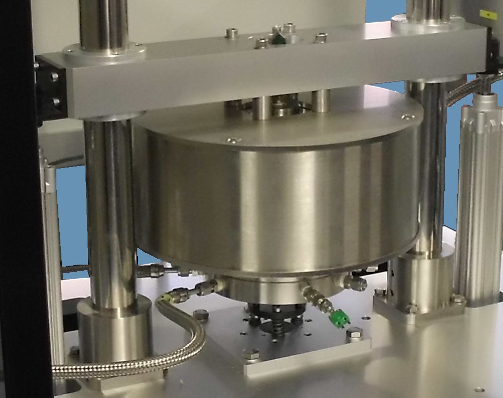
Heating mantle lowered ready for test The autoclave is heated by an electric furnace, which is raised and lowered by pneumatic actuators.
Autoclave Operation
The autoclave is design to operate under two separate regimes:
• Gas over water
• Steam over water
Two severe service Back Pressure Regulators are included, one with an operating range 0 – 2 bar and one, 0 – 25 bar, with a manual changeover valve between for selection. The lower pressure valve is typically used for pre-test purge with inert gas to deoxygenate the water. The high pressure valve is used for setting and controlling the maximum pressure in the vessel, during operation.
The recommended method of operation is gas over water, with nitrogen as the gas. A fixed volume of water is added to the vessel, with the free space then purged with nitrogen. After purging, the vessel is pressurised with nitrogen, to the required test pressure. As the vessel is heated, nitrogen is released, at the pressure set on the regulator.Control and Data Acquisition
COMPEND 2000 control and data acquisition system, providing control of voice coil actuator, supervisory control and data recording of autoclave and real-time measurement of specimen motion.
-
Technical Specifications
Performance Specification Maximum water temperature: 220°C Maximum pressure: 24 bar Maximum contact load: 2 N Stroke: 20 to 200 microns Frequency: 20 to 60 Hz Autoclave Specification Total internal volume: 1.2 litres Maximum working pressure: 50 barg Design pressure: 55 barg Maximum working temperature: 250°C Design Temperature: 300°C Vessel Construction: No welding procedures Vessel machined from solid Hastelloy bar Base machined from Certified (EN 10204 3.1) SA 479-316 stainless steel Closure type: Flanged and bolted Design Code: ASME VIII. Div 1 (NCS) Pressure Vessel Code Design Code: European Harmonised Standard BS EN 13445-1:2002 Legal Requirement: Pressure Equipment Directive 97/23/EC (PED) May 2002 PED Classification: Conformity assessment module H or G Category: Cat III. Table 1 Certification: Unit CE marked Mounting Style: Fixed base – removable vessel chamber External fittings and valves: Certified (EN 10204 3.1) SA 479-316 Stainless steel. Bolting material: Certified (EN 10204 3.1) SA193 B8M / SA194 8M (Temperature critical dependency) Safety pressure relief: Valve (PED compliant) conforming to the requirements of BS 6759-1/2 1984 set at 2 barg supplied complete with individual calibration certificate Valve (PED compliant) conforming to the requirements of BS 6759-1/2 1984 set at 25 barg supplied complete with individual calibration certificate Pressure regulation: Severe service Back Pressure Regulator 0 – 2 barg Severe service Back Pressure Regulator 0 – 25 bar Bursting disc body: Fitted with, P.T.F.E. protected, nickel bursting disc to the requirements of B.S. 2915:1990. Certification: Pressure vessel designed in accordance with ASME VIII. Div 1 (NCS) Pressure Vessel Code and issued with full hydrostatic pressure test, gas test and material certificates (EN 10204 3.1.B) Third party inspection complying with the European community Pressure Equipment Directive 97/23/EC (PED) May 2002, including independent inspection at various stages of manufacture and subject to a witnessed hydrostatic test complete with test certification and authorised CE plaque. Voice Coil Actuator System Maximum Stroke: 4 mm (+/- 2 mm) Maximum Frequency @ Maximum Stroke: 50 Hz (continuous) Peak Driving Force: 1512 N Continuous Stall Driving Force: 387 N Displacement Measurement Type: Extreme environment non-contact displacement sensor Target: Non-magnetic stainless steel Offset: 0.025 mm Range: 1.0 mm Input: +/- 15 VDC Output: 0-2 VDC Calibrated: Ambient and 220°C Best linearity @ 220°C Controlled Parameters Frequency Stroke Temperatures Pressure Number of Cycles Recorded Parameters Frequency Stroke Temperatures Pressure Number of Cycles Services Electricity: 380/415 V, three phase, 50/60 Hz, with neutral and earth, 7.5 kW Installation Floor-standing machine: 900 mm x 600 mm deep x 2000 mm high, 250 kg Bench-mounting cabinet: 530 mm x 420 mm x 300 mm high, 20 kg Packing Specifications: 2.2 m3, GW 600 kg, NW 450 kg -
Index Tags
autoclave fretting crossed cylinder – specials environments fretting fretting wear fuel rod high pressure testing high pressure water special environments superheated water -
Download the Machine Leaflet

Call us on +44 (0) 1635 298279
Email : info@phoenix-tribology.com
Email : info@phoenix-tribology.com