-
Background
The Gas Jet Erosion Rig is based on an experimental technique developed by Dr. I M Hutchings Cambridge University Department of Materials Science and Metallurgy, in association with Dr. A. Ramamurthy and Freese Enterprises in the USA. It is manufactured by Phoenix Tribology Ltd under license.
The TE 68 may be used to determine the wear coefficient of hard and soft coatings and monolithic materials by erosive wear of a gas borne stream of particles.
Erosion is an important wear mechanism in industrial applications. Despite the existence of ASTM and DIN standard methods, everyone has their own way of doing erosion tests. ASTM G 76 “Standard Practice for Conducting Erosion Tests by Solid Particle Impingement” in fact acknowledges that the one single laboratory test may not be sufficient to evaluate expected service performance. Actual erosion service can involve a range of particle sizes, velocities, attack angles & environments, all of which influence erosion rate.
Key parameters to define and control in an erosion test are as follows:- Particle velocity. This is not the same as the air velocity, but is often assumed to be.
- Particle mass flow rate
- Nozzle wear
- Particle spread from nozzle
- Size and shape of particle
- Angle of impact of the particles
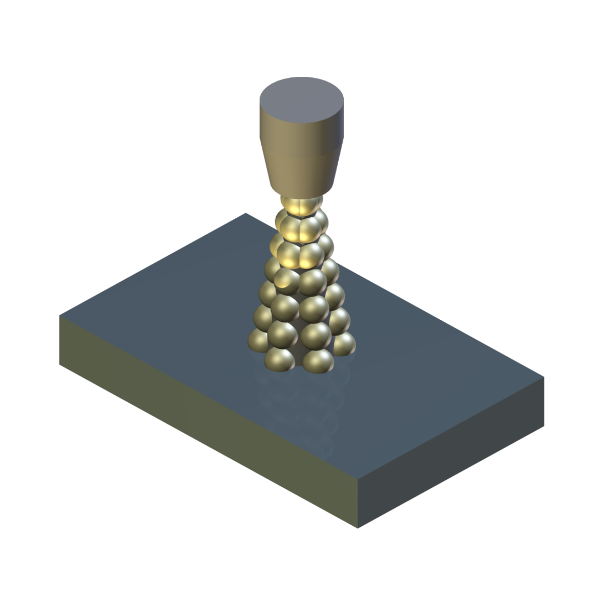
One particular feature of the ASTM G76 method is the fact that the very small jet diameter (1.5 mm) results in the particles “drilling” into the surface. The standard states that the depth of penetration should not exceed 1 mm. This is a deep hole in any surface and in fact the deeper the penetration, the more the physical state of the erosion jet will change (due to interaction of the particles hitting the surface and rebounding). These very severe test conditions are not appropriate for coatings, for which the test must be designed to determine the wear of the coating, not the substrate material.
A related problem of a small nozzle size such as that defined by ASTM is that the nozzle will wear. This results in a change in the shape of the particle stream as it emerges from the nozzle and this will result in variability in the data.
ASTM G 76 defines a nozzle of 1.5 mm inner diameter and 50 mm long. This small nozzle size means that there is a large back-pressure and the abrasive sand has to be fed under pressure to achieve the required mass flow rates (2 +/- 0.5 g/minute). A pressure of 20 p.s.i. (1.4 bar) at the entry to the nozzle is typically required to give a particle velocity of 30 m/s.Description
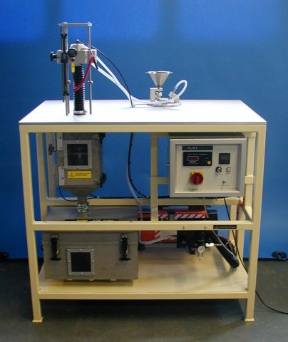
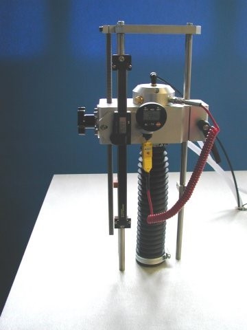
The TE 68 Gas Jet Erosion Rig uses a larger nozzle of 4.7 mm bore and 300 mm long. This means that operating pressures are very much lower.
The nozzle does not have to be manufactured from Tungsten Carbide, instead they are made from standard seamless drawn type 304 stainless steel tubing. The internal surface finish can be carefully controlled and the cost of replacement nozzles when necessary is very low.
The larger nozzle diameter results in a wider spread of particles which is therefore more suited to erosion testing on coatings as well as solid material: there is less of a tendency to “drill” holes in the surface, In addition, there is a much smaller influence of rebounding particles on the impinging jet, resulting in a better controlled erosion process.
The larger nozzle size also permits a wider range of particle types to be used in the course of testing, allowing better simulations of real erosion conditions.
The mass flow rate is controlled by use of a rotating grooved disc and particles are delivered from the groove to the air stream by way of venturi suction. Mass flow rate is adjusted by controlling the speed of the rotating disc. Particles are fed from a simple hopper under gravity into the groove.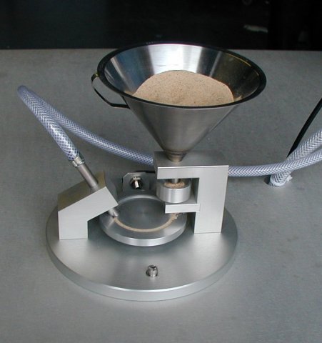
Features
- Vertical traverse for the nozzle: provides variable nozzle to target stand-off distance which influences the size of the eroded area.
- Different nozzles may be accommodated: provides ability to change the particle plume dimensions and the velocity range
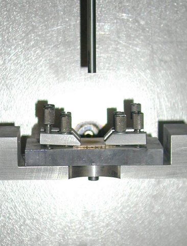
- Large test chamber with sample mount (typical sample size 50 mm x 50 mm) that can be angled to the flow direction: by tilting the sample stage, the angle of impact of the particles can be changed and this will influence the erosion process.
- Optional air heating system: this permits “hot” tests up to 100 °C
Standard Performance
The velocity of the particles is determined by the air pressure and length of nozzle. A wide range of velocities is covered from 25 to 80 m/s and a feed rate of 0.2 to 2 g/minute.
Enhanced Performance
By enclosing the particle feed assembly in a small chamber and applying a pressure of up to 4 bar, the particle velocity can be increased from a nominal maximum of 80 m/s to 120 m/s. The pressure differential between the mixing chamber and the nozzle discharge remains approximately 1 bar, indicating a pressure drop of 3 bar between the particle feed chamber and venturi injector.
A definitive investigation of the relationship between the pressure differentials between the feed assembly chamber, the mixing chamber, the injector upstream pressure and the nozzle discharge pressure and the resulting particle flow rate has yet to be completed. However, the addition of the feed chamber, which is now fitted as standard, does produce a measurable increase in particle velocity under certain user adjusted test conditions. -
Technical Specifications
Standard Performance Velocity: 25 to 80 m/s at 1.5 bar pressure Feed Rate: 0.2 to 2 g/minute. Enhanced Performance Maximum Velocity: 120 m/s at 4 bar pressure Service Requirements Clean, dry air: 1.5 bar and 3.5 c.f.m. flow rate for speeds up to 80 m/s 4 bar and unspecified flow rate for speeds up to 120 m/s Electricity: 220/240V, single phase, 50 Hz, 1.5 kW Installation 1,000 mm wide x 1,200 mm high x 400 mm deep on floor standing frame -
Index Tags
abrasion & erosion test machines brittle materials coatings erosion gas jet erosion gauge corner cracking paint films wear by hard particles -
Download the Machine Leaflet
Call us on +44 (0) 1635 298279
Email : info@phoenix-tribology.com
Email : info@phoenix-tribology.com