-
Description
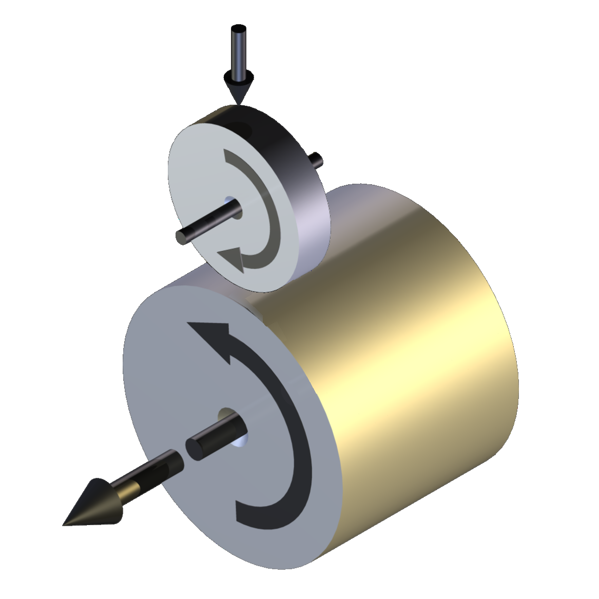
The TE 72 Two Roller Machine has two motors, one to provide the input power and one to absorb the transmitted power. The design is of the “over-hung” roller type, with test rollers fitted over-hung on the end of the machine test spindles, as opposed to the “fully supported” arrangement, in which the test rollers are mounted on shafts between bearings, as with the TE 74 Two Roller Machine.
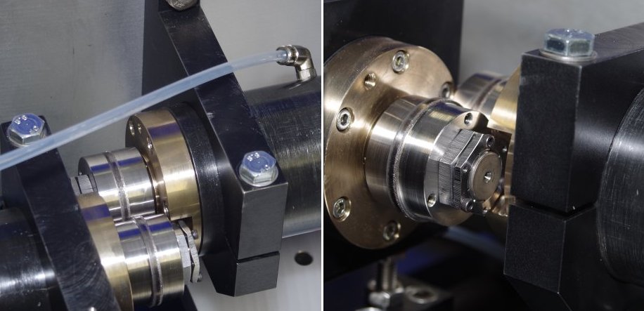
The advantages of the over-hung design are, firstly, that the test rollers are readily accessible and can be removed without removing a bearing and, secondly, that such designs allow variable shaft centre distances, thus allowing the maximum flexibility when it comes to the choice of test roller diameters. The principal disadvantage of the over-hung design, when compared with the fully supported design, is that the arrangement produces a cantilevered load on the test spindle bearings, thus limiting the maximum load capacity of the machine, compared with that achievable with the latter arrangement.
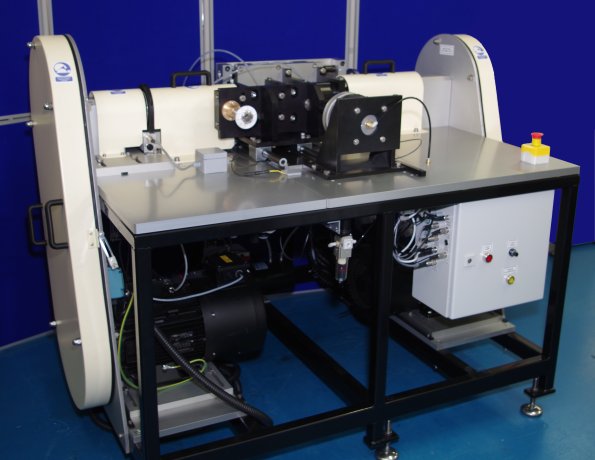
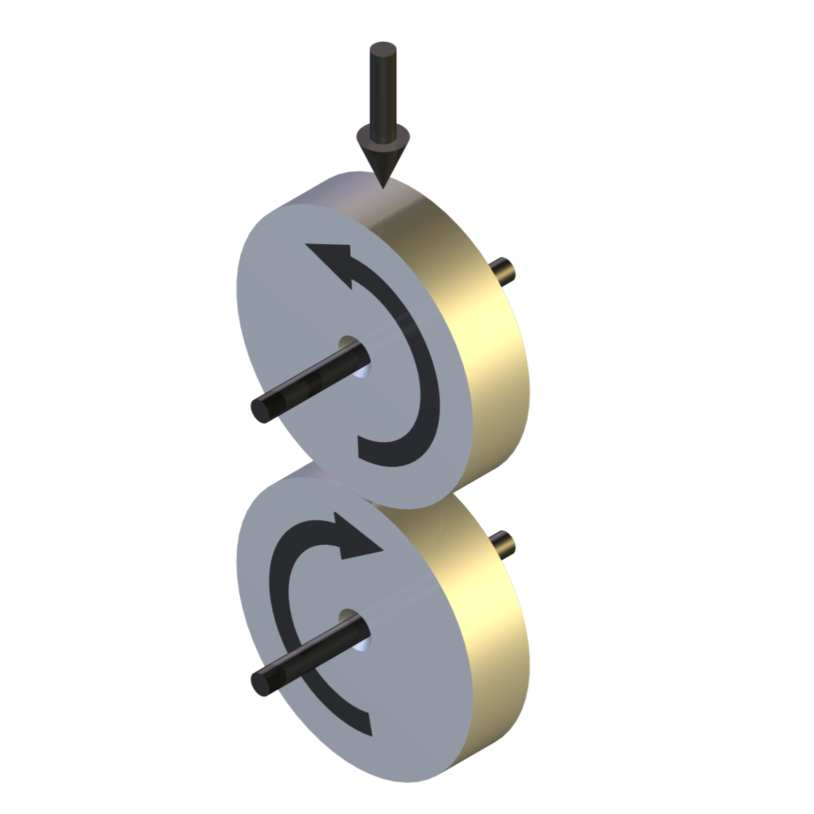
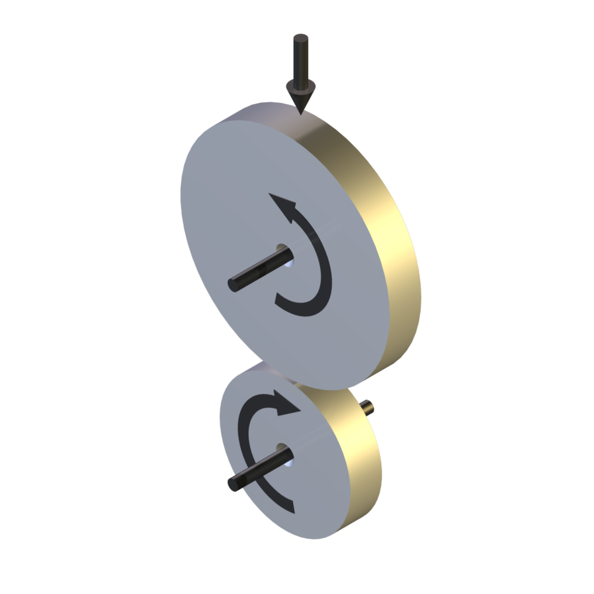
The TE 72 Two Roller Machine has two a.c. vector motors, each connected by timing pulley to a test assembly. One drive incorporates an in-line torque transducer, which is connected via a cardan shaft to a roller spindle, mounted in turn on a radially oriented, linear slide. The cardan shaft and slide permit horizontal displacement of the roller spindle, allowing load application and adjustment for different diameter rollers. The spindle assembly includes an alignment mechanism that allows the spindle to be rotated in a vertical horizontal plane about the point of contact, allowing introduction or removal of small amounts of skew.
The second roller spindle is mounted on an axially oriented, servo motor driven, linear slide, which allows axial displacement of one roller relative to the other. The slide is mounted on a bracket, which is, in turn, mounted on the machine base plate, through a pivot. This allows adjustment for line contact alignment of the rollers. The roller spindle is connected through a telescopic cardan shaft to a lay-shaft and thence via belt drive to the second motor. Application of axial movement on the roller contact, when in motion, allows investigation of the effects of lateral movement on traction coefficient, using a roller on drum test configuration.
The use of an in-line torque transducer for traction measurement is subject to parasitic losses associated with the roller spindle bearings. These losses a very small but may be quantified by running the unit under conditions of zero slip at different speeds and temperatures. The roller spindles, which are oil fed, are sealed with labyrinths, thus eliminating parasitic losses associated with conventional sliding seals.
Load is applied by means of a servo controlled pneumatic bellows with force transducer feedback. The motors are a.c. and powered by vector drives allowing precise control of speed. Power is re-circulated electrically via a common d.c. link between the drives, upstream of the frequency inverter stages. Total power requirement is thus limited to the system losses.
For control purposes, one drive is designated as master with the second drive deriving its speed set point, adjusted for the required slip ratio, from the master drive.
A vibration sensor is provided for detecting surface fatigue failure. One roller housing is electrical isolated and both spindles are provided with brushes for electrical contact potential measurement.Test may be run either dry or jet lubricated. For fluid tests, an optional fluid service module is available, incorporating a sump tank with immersion heater, delivery pump and oil to water heat exchanger for cooling.
Control and Data Acquisition
Control and data acquisition are implemented via host PC running COMPEND 2020 Windows compatible software, in conjunction with a Phoenix Tribology USB micro-controller interface.
Automatic control is implemented via user programmable test sequences. Manual control is implemented using on screen toggles. Data is stored to hard disc in either .csv or .tsv file formats.
-
Technical Specifications
Standard Two Roller Configuration
Type: Circulating power Overhung roller Spindles opposed Variable shaft centre distance Contact: Line, point or elliptical contact Geometry: Roller on Roller Maximum Skew Angle: +/-3 degrees Test Conditions: Pure Rolling Sliding/Rolling Environment: Dry & Lubricated Maximum Roller Diameter: 120 mm Minimum Roller Diameter: 50 mm Maximum Shaft Centre Distance: 120 mm Minimum Shaft Centre Distance: 50 mm Maximum Roller Thickness: 30 mm Maximum Load: 5 kN Slide-Roll Ratio: 0 – 200 % (pure rolling to pure sliding) Roller Temperature: Ambient to 150°C Temperature Measurement: Qty 2: Non-contact IR Maximum Motor Power: 7.5 kW @ 1500 rpm Maximum Motor Speed: 3000 rpm Drive Ratios: 2:1, 1:1, 1:2 Maximum Roller Speed: 6000 rpm with 2:1 Belt Ratio Maximum Torque 2:1 Belt Ratio: 24 Nm @ 3000 rpm Maximum Torque 2:1 Belt Ratio: 12 Nm @ 6000 rpm Maximum Torque 1:1 Belt Ratio: 48 Nm @ 1500 rpm Maximum Torque 1:2 Belt Ratio: 96 Nm @ 750 rpm Indexing Roller on Drum
Contact: Elliptical contact Geometry: Indexing Roller on Drum Maximum Drum Diameter: 60 mm Minimum Drum Diameter: 50 mm Maximum Roller Diameter: 120 mm Minimum Roller Diameter: 100 mm Maximum Axial Travel: 30 mm Controlled Parameters
Motor speed Motor speed difference Applied load Test duration Measured Parameters
Motor speed Motor speed difference Number of revolutions Applied load Transmitted torque Electrical Contact Resistance Roller surface temperature (dry) Roller surface temperature (dry) Vibration sensor output Calculated Parameters
Traction force Coefficient of Traction Friction Power Services
Electricity: 380/415V, three phase plus neutral, 50/60 Hz, 16 kW Clean, dry air: 4 cfm at 8 bar (120 psi) Mains water and drain: 10 l/min (typical) -
Index Tags
-
Download the Machine Leaflet

Call us on +44 (0) 1635 298279
Email : info@phoenix-tribology.com
Email : info@phoenix-tribology.com