-
Background
The TE 73 family of machines dates back to original Plint and Partners Ltd designs from the 1960s. These machines are all to the “overhung” roller design in which test rollers are mounted on the end of spindles and in which the spindle housings are mounted adjacent to each other. This arrangement has the obvious benefit of making the rollers much more accessible than in other configurations. There is, however, one significant consequence of this arrangement and that is that, with equal sized rollers, the roller diameter must obviously be greater than the spindle housing diameter. In other words, the diameters of the spindle housings fix the minimum shaft centre distance and thus determine the minimum diameter of roller that can be accommodated. This configuration is thus only suitable for experiments using quite large diameter rollers, the consequences of which are:
- The larger the diameter, the greater the torque generated, for a given load and traction coefficient.
- The larger the diameter, the more expensive the rollers become to manufacture.
Despite these caveats, it is of course worth noting that there are known scale effects with two roller or twin disc tests, so in some circumstances, adequate correlation can only sensibly be achieved when performing tests with rollers of sufficient size. For obvious reasons, tests demanding high surface speeds are best achieved with larger diameter rollers, likewise tests requiring a long hertzian contact length. Finally, if large amounts of frictional heat are to be dissipated in the contact, the larger the roller, the larger the thermal mass and surface area and the better the heat dissipation. Small rollers can become unrepresentatively hot!
Legacy Design
 TE 73 – Original Design
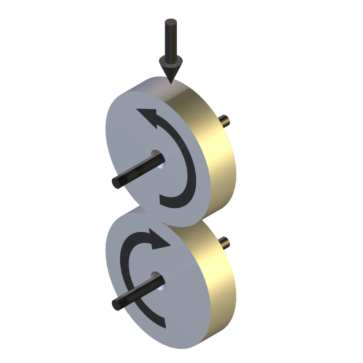
In the original design, two roller specimens are mounted one above the other on the ends of parallel test shafts, which are connected to a helical gear pair at the rear of the machine. This is thus a “four-square” or “back-to-back” design. The lower shaft is driven by a variable speed motor, through a belt drive. The motor supplies only the losses in the loop, not the full tractive power which is locked into the torque loop.
Slip percentages from 0% (pure rolling) to 8% are selected by installing an appropriate gear pair. The test rollers have a crowned profile giving a well-defined circular contact zone and high Hertzian contact pressures.
Current Design
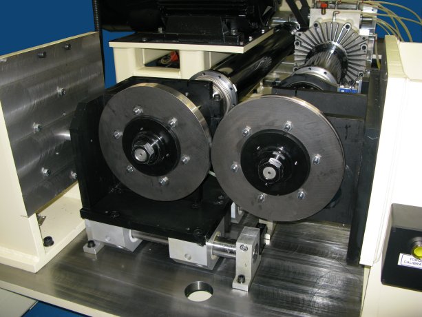
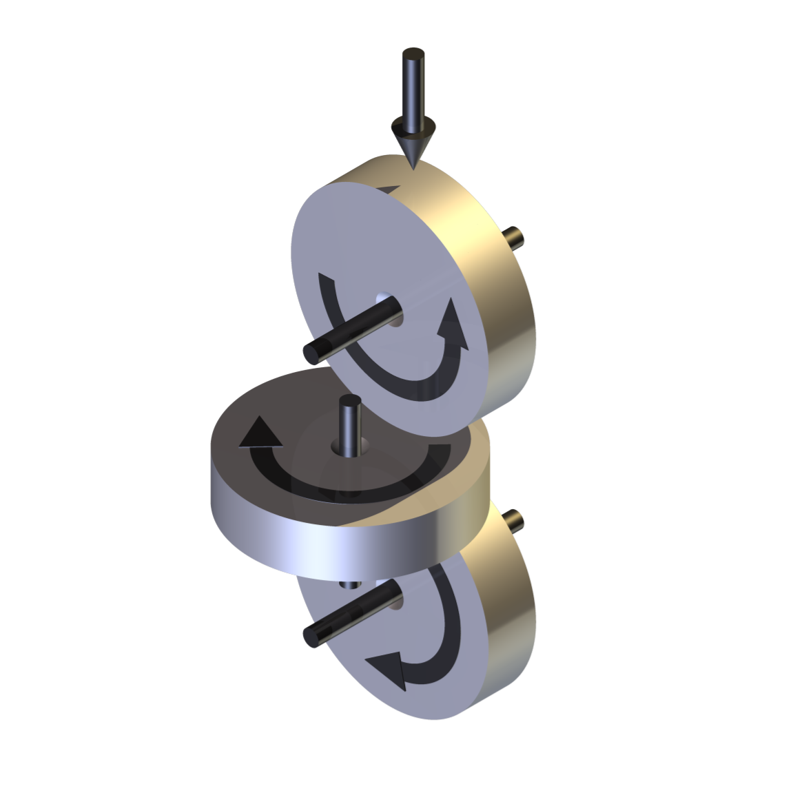
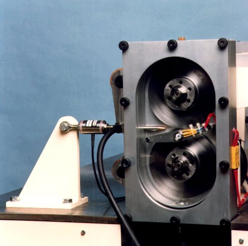
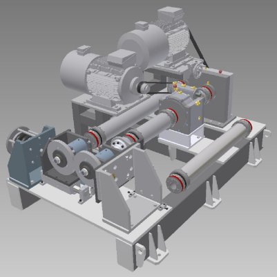
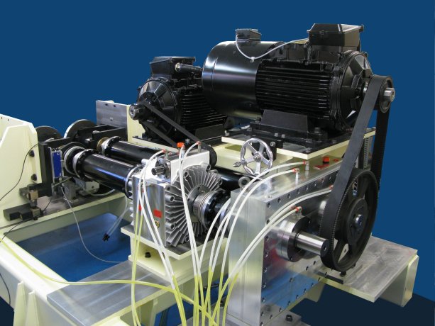
In the current TE 73H design, the test rollers are mounted on a horizontal axis, side-by-side,
with one spindle housing mounted on a linear slide, allowing it to be indexed towards, and
hence loaded against, a fixed spindle.Roller spindles are oil lubricated from a lubricant service unit. Seal friction is eliminated by the use of non-contacting labyrinth seals. One roller assembly is pivoted with a mechanism to achieve up to 1% skew adjustment.
The TE 73H is a back-to-back gear unit designed to operate with large diameter discs, thus
generating high torques and transmitting high levels of power through the roller contact. The
minimum roller diameter is 280 mm and the maximum diameter is 320 mm. Two drive
arrangements are provided, one for low rotational speeds involving continuously variable slideroll ratio and one for high speeds with fixed slide-roll ratio.
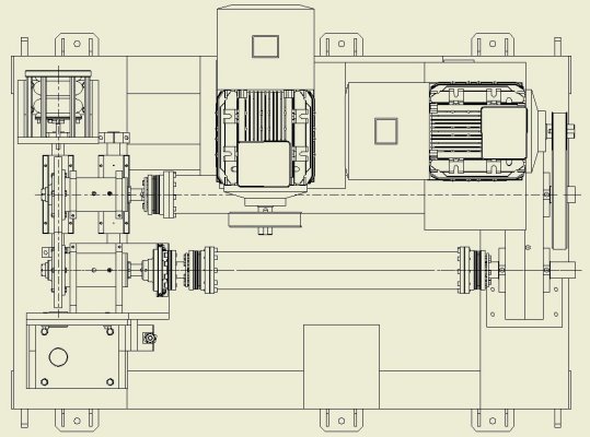
 TE 73H – Variable Slide-Roll Range
At low speeds, up to a maximum of 500 rpm, a speed modulating, two-stage, epicyclic gear-box is included in the torque loop. By driving the ring gear on the output stage of the gear-box, the output speed can be adjusted by +/-22 rpm, hence, for an input speed of, say, 100 rpm, the output speed can be adjusted to 100 +/-22 rpm and 500 rpm to 500 +/-22 rpm. The torque loop is completed with a two axle, close ratio, gear-box.
The torque loop system losses are provided by a 30 kW vector motor rotating the loop through an input shaft on the close ratio gear-box. A second 30 kW motor drives the ring gear on the epicyclic gear-box, thus allowing speed modulation.
It should be noted that although the two motors are powered by twin vector drives, each drawing power from a common d.c. bus, thus potentially allowing electrical power recirculation, in this case both motors are actually driving, not one motor driving and the other acting as a generator.
 TE 73H – Fixed Slide-Roll Range
The speed limit of 500 rpm is determined by the operating limits of the speed modulating gear-box. Above this speed, the speed modulating gear-box is taken out of the torque loop and its associated motor disabled. At speeds up to 1780 rpm (a surface speed of 100 kph with 300 mm rollers) the machine operates with a fixed slide-roll ratio, set by the gear pair in the parallel shaft gear-box. Gear-boxes with ratios from 100:100 to 100:90 are available. It must of course be remembered that these gear-boxes are used at the lower speed range in conjunction with the speed modulating gear-box, an ideal combination being the latter with a 100:99 parallel shaft box.
Control and Data Acquisition
Control and data acquisition are implemented via host PC running COMPEND 2020 Windows compatible software, in conjunction with a Phoenix Tribology USB micro-controller interface.
Automatic control is implemented via user programmable test sequences. Manual control is implemented using on screen toggles. Data is stored to hard disc in either .csv or .tsv file formats.
-
Technical Specifications
Type: Circulating power Overhung roller Spindles parallel Limited variable shaft centre distance Contact: Line or point contact Test Conditions: Pure Rolling Sliding/Rolling Environment: Dry & Lubricated Standard Roller Diameter: 300 mm on 300 mm Maximum Roller Thickness: 30 mm Maximum Shaft Centre Distance: 320 mm Minimum Shaft Centre Distance: 280 mm Maximum Load: 21 kN Continuously Variable Slide-Roll: 0 to 500 rpm Speed Modulation: +/-22 rpm Fixed Slide-Roll: 0 to 1800 rpm Roller Temperature: Ambient to 150°C Maximum Motor Power: 30 kW @ 1500 rpm Maximum Motor Speed: 3000 rpm Maximum Spindle Speed: 1800 rpm Maximum Roller Torque: 1200 Nm Maximum Transmitted Power: 225 kW @ 1800 rpm Speed Modulation Gear-box: Rated at 1200 Nm at 0 to 500 rpm Plate Gear-box /Gear-boxes: Rated to 225 kW at 1800 rpm on 300 mm centres Available Gear-box Ratios: 100:100 to 100:90 Spin Adapter: 47.5 Nm Maximum Surface Speed (150 mm Roller): 22 ms-1 Spin Adapter: Optional Controlled Parameters
Motor speed Motor speed difference Applied load Test fluid temperature Test duration Measured Parameters
Motor speed Motor speed difference Applied load Transmitted torque Lubricant inlet temperature Test bath outlet temperature Vibration sensor output Electrical contact resistance Services
Electricity: 380/415V, three phase plus neutral, 50/60 Hz, 75 kW Clean, dry air: 4 cfm at 8 bar (120 psi) Mains water and drain: 10 l/min (typical) -
Index Tags
-
Download the Machine Leaflet

Call us on +44 (0) 1635 298279
Email : info@phoenix-tribology.com
Email : info@phoenix-tribology.com