-

Background
The Rubber Friction Test Machine offers the ability to investigate fully the frictional behaviour of rubbery materials both in dry and lubricated environments. It can also be used to study the friction of cosmetic products by using a suitable model for human skin.
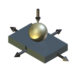
Typical contact configurations are ball on rubber flat and plate on rubber hemisphere. Thin rubber sheet samples may be tested by clamping them against a rubber backing. Other items such as threads, gloves and seals may be tested by the provision of suitable holders.
The TE 75 was developed under licence from Rubber Consultants, part of the UK Malaysian Rubber Producers Research Association. The control unit includes a SLIM 2000 Serial Link Interface Module and COMPEND 2000 Windows based control and data acquisition software.
In rubber the friction force depends strongly on the real contact area between the rubber and counter surface, the interfacial shear strength and the deformation properties of the rubber . Each of these factors depends on others. The area of contact relates to the hardness and surface roughness, the applied load and the relative radius of curvature of the contacting surfaces. The interfacial shear strength depends on the polymer itself and the presence or absence of lubricants, solid or liquid.
For the sliding of rubber against a rough (abrasive) surface such as silicon carbide paper there is a gradual change in friction with sliding rate. This is understood in terms of a combination of effects including adhesion, ploughing hysteresis and tearing.
To make measurements of the friction coefficient of rubber it is important to have a well-defined contact geometry. A flat-on-flat geometry tends to give poor repeatability due to problems associated with achieving and holding the surfaces flat against each other. This requires both the production of smooth, flat surfaces and also a rigid test machine. Even if the specimens can be held in the correct orientation there are still problems associated with frictional tilt during motion.
This tilt is a direct result of the flexibility or low elastic modulus of the rubber material. A metal ball on a pivoted arm loaded against a rubber flat will indent to a considerable distance. This indentation gives rise to two effects. First the line of action of the friction force shifts out of the horizontal plane. Second the large contact area gives rise to high friction force, even at quite modest normal loads. In both these respects rubber differs from harder materials such as metals and ceramics and this must be catered for in the machine design.
The TE 75 was designed with this specific effect in mind. The friction force measurement is independent of the degree of misalignment or indentation of the samples. This was achieved by having the load and force axes at right angles and by allowing the link to the force transducer to slide vertically. An additional requirement was to have sensitive force measurement at small normal loads to address aspects of friction due to adhesion.
Tests can be carried out with flat-on-flat and ball-on-flat (or reverse). The ball-on-flat geometry has been adopted by a number of researchers and they report much improved reproducibility of friction data compared to flat-on-flat geometry. The area of contact is defined by the elastic deformation of the rubber on a macro scale and this makes the contact effectively self-aligning.
Variable test parameters include speed, stroke, sliding path, load, contact geometry, contact time or dwell period (dwell before initial sliding), lubrication, gaseous environment, temperature and relative humidity.
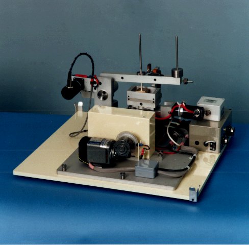
Description
The fixed upper sample is loaded by dead-weights onto a sample mounted on a single axis linear traverse. As the lower sample moves the friction force on the upper sample is measured.
The TE 75 has a trunnion and gimble mounted loading beam, counterbalanced both to give a neutral balance and to bring the centre of gravity onto the contact plane. Load is applied by dead weights in a range from 0.1 N to 20 N.
The load beam lift/drop is servo controlled so that the load can be applied at a specific point in the test. The program can also introduce a dwell between load application and movement. This dwell period can be crucial in determining the start-up friction in elastomers as the adhesive forces will increase the contact area over time.
The loading beam is restrained by a strain gauge force transducer in a sliding link. This link ensures that only the tangential component of force in the contact (the friction force) is measured even with the large deflections associated with rubber test pieces.
Dual Axis Traverse
The TE 75 has X and Y axis movement with linear positional feedback. Tangential (friction) force measurement is in the X direction. The axes are crossed linear slides with 1 mm pitch lead screws and are driven by geared dc motors. The X-AXIS drive has interchangeable belt reductions to give an overall speed turn-down of 1000:1. The Y-AXIS is direct coupled to a smaller motor giving a maximum index speed of 10 mm/min.
The control strategy assumes that X = 0, Y = 0 is at the very centre of lower test specimen. Therefore all X traverses begin at a negative position equal to half the selected stroke. The operator only needs to select the required stroke, the software derives the starting point.
The operator selects the required starting point for the Y AXIS indexing and this is termed the INITIAL Y OFFSET. If this is set to 0 the Y slide will begin at the centre of the specimen. To reach the edge of the specimen, INITIAL Y OFFSET = (Width of specimen)/2.
By combining the X-AXIS movement with the Y-AXIS indexing function a number of motion types can be configured. These are defined as follows:
INDEX = 0 The outward and return strokes are at the same Y position. This provides simple reciprocation along one track.
INDEX > 0 The Y AXIS is indexed between each stroke by an amount defined by the Y INDEX DISTANCE, thus each outward and return stroke is separated on the surface. The wear track resembles a square wave.
LOOP In this case a closed loop is defined whose width is defined by the Y INDEX DISTANCE and length by the STROKE LENGTH.
In this way a test may be performed both on continuously fresh surface or on the same track approached from either direction. This latter feature is important for elastomers which show a direction dependence of wear due to plucking and tearing.
Test Environment
Since both samples are simple and the fixing arrangements are flexible a variety of shapes and counter-surface materials may be accommodated. The plate sample size is typically 25 mm square. The fixture for the lower (moving) specimen includes an electrical resistance heater and two thermocouples for temperature measurement and control above ambient conditions.
The machine is provided with a plastic safety cover, which also acts as a chamber for the user to run under controlled humidity conditions. An ambient temperature and humidity sensor is mounted on the machine base inside the chamber.
TE 75/C Cooler Pad and Laboratory Chiller
This test assembly replaces the standard fixed specimen heater block assembly with a cooler pad. Used in conjunction with a Laboratory Chiller unit with water/glycol mixture as the coolant, temperatures from -25°C to ambient may be achieved. To avoid ice formation, this adapter is best used in conjunction with a simple desiccant dehumidifier system used in conjunction with a controlled air supply.
Control and Data Acquisition
Control and data acquisition are implemented via host PC running COMPEND 2020 Windows compatible software, in conjunction with a Phoenix Tribology USB micro-controller interface.
Automatic control is implemented via user programmable test sequences. Manual control is implemented using on screen toggles. Data is stored to hard disc in either .csv or .tsv file formats. -
Technical Specifications
Contact Configurations: Ball on Plate Plate on Plate Plate on Hemisphere Customised specimens possible Normal Load: 0.1 to 50 N Friction Force Range: 0 to 50 N X Axis Speed Ranges: 0.9 mm/s to 10 mm/s 0.05 to 0.9 mm/s 0.01 to 0.09 mm/s X Stroke: 1 to 50 mm Y Index Speed: 10 mm/min maximum Y Index: +/- 9 mm in steps of 0.5 mm Temperature Range: ambient to 100°C Dwell (time delay): User selected in seconds up to 8 hours Humidity Sensor: 10 to 90% RH Temperature Sensor: J-type thermocouple Heating Power: 150 W Interface: Phoenix Tribology USB micro-controller interface Software COMPEND 2020 Motor: 125 W dc TE 75/C Peltier Cooler Minimum Temperature: -15°C (ambient water cooled) Minimum Temperature: -30°C (chiller water/glycol cooled) RE 75/C Laboratory Chiller Working Fluid: 50:50 Water/Glycol Fluid Temperature: -35°C Controlled Parameters X Position X Axis Speed Y Position Y Axis Speed Temperature Dwell Period Test Duration Measured Parameters X Position Y Position Humidity Temperature Friction Friction Coefficient Services Electricity: 220/240 V, single phase, 50 Hz, 720 W 110/120 V, single phase, 60 Hz, 720 W Installation Bench-mounting machine: 570 x 600 x 600 mm high, 40 kg Bench-mounting cabinet: 530 x 530 x 240 mm high, 20 kg Packing Specification: 0.59 m3, GW 120 kg, NW 70 kg -
Applications
-
Publications
Paper # 75 Friction Test Machines for Rubbery Materials Alliston-Greiner A F, Tribotest Journal, 1(1), 1994, 63-75. Paper # 76 New Rubber Friction Test Machine Roberts A, Rubber World, 209 (4), 1994, 16-18. Paper # 337 Modification of epoxidised natural rubber film surface by polymerisation of methyl methacrylate C Amornchaiyapitak, W Taweepreda European Polymer Journal Volume 44, Issue 6, June 2008, p. 1782-1788 Paper # 426 An Approach of Frictional Characterization for Elastomers and Elastomeric Composites M Scherbakov, MR Gurvich Journal of Elastomers and Plastics, Vol. 35, No. 4, 335-356 (2003) Paper # 778 Reduction of surface friction of natural rubber film coated with PMMA particle: Effect of particle size W Anancharungsuk, W Taweepreda Journal of Applied Polymer Science 2010 Volume 115, Issue 6, p. 3680–3686 -
User List
Launched 1995
Pyung Hwa Industrial Korea Goodyear Luxembourg L.R.C. Hospital Products (Malaysia) Ltd Malaysia Linatex Europe Ltd Malaysia The Rubber Research Institute of Malaysia Malaysia Unilever Netherlands Chulalongkorn University Thailand Procter & Gamble (Health & Beauty Care) Ltd UK Procter & Gamble (Health & Beauty Care) Ltd UK Rubber Consultants (MRPRA) UK London International Group UK Bridgestone Research USA Rexco Hanoi Vietnam -
Download the Machine Leaflet