-
Description
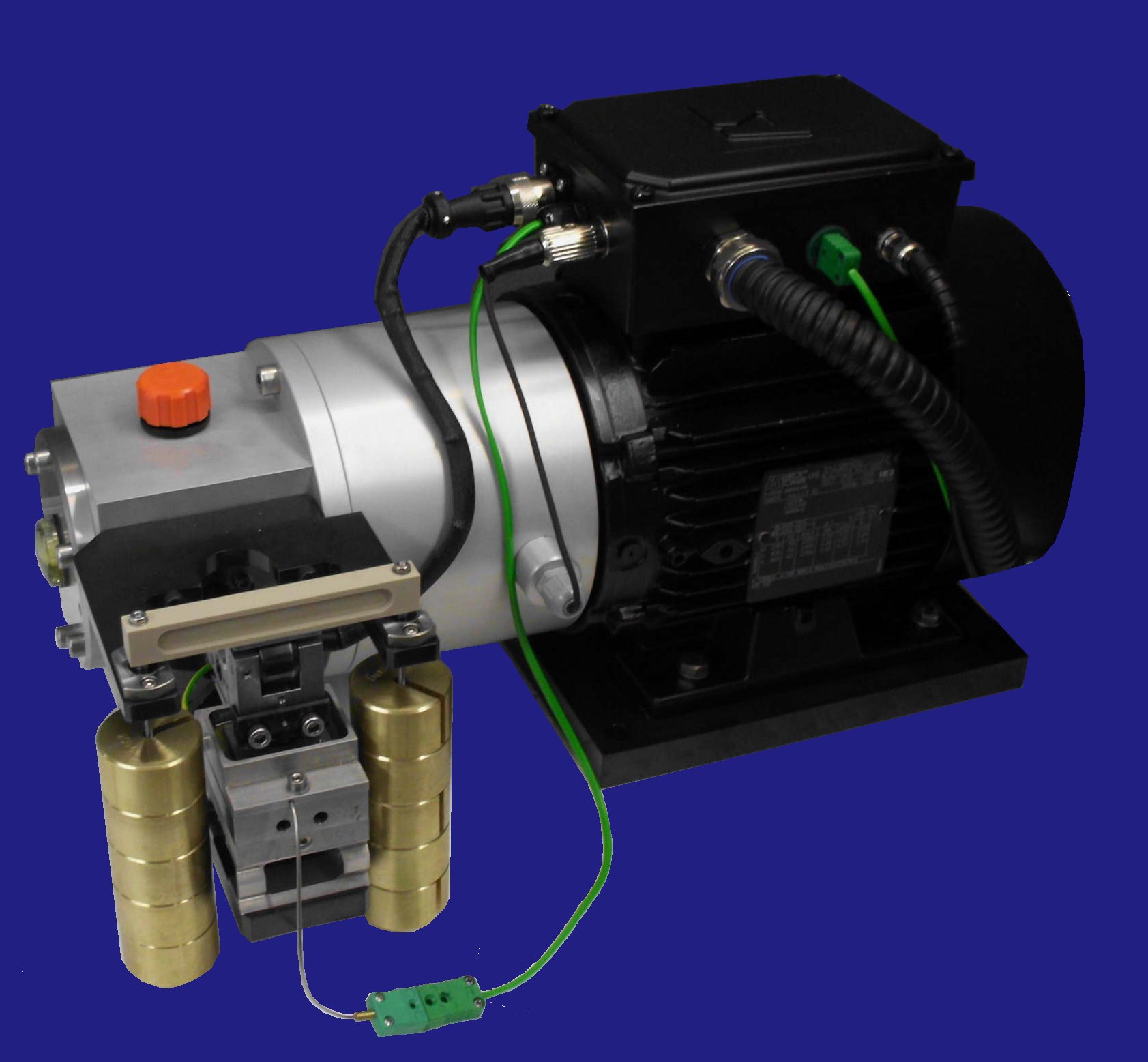
The TE 81 Bench-top Reciprocating Tribometer is a single station version of the TE 90 Multi-Station Reciprocating Tribometer. It incorporates a test station with heater pad. Load is applied via servo pneumatic actuator (formerly, manually, by means of dead weights).
The TE 81 has a control unit incorporating a SUPERSLIM Serial Link Interface Module, which is connected to a host PC with COMPEND 2000 sequence control and data acquisition software installed. The system provides sequence control of load, frequency and temperature, plus data acquisition of measured parameters including load, RMS friction, friction noise, contact potential and temperature.Moving Specimen
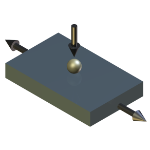
The moving specimen is mounted in a carrier. A number of different geometries can be accommodated by using a range of simple clamping fixtures.
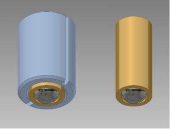
6 mm ball carrier in standard sleeve
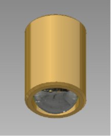
10 mm ball carrier
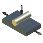
6 mm diameter line contact tooling
The specimen is oscillated mechanically against the fixed lower specimen. The mechanical drive comprises a motor driven cam and scotch yoke assembly, providing pure sinusoidal motion. The drive mechanism runs inside an oil bath.
The stroke length is altered manually by changing the cams. Five cams are provided as standard allowing strokes to be set from 0 to 5 mm in 1mm increment.
The moving specimen is loaded against the fixed specimen through a loading yoke, incorporating a servo controlled pneumatic cylinder, which transmits the normal force directly onto the moving specimen by means of a ball and socket connection between yoke and reciprocating head.Fixed Specimen
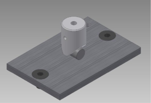
The fixed specimen is located in a stainless steel reservoir. The reservoir is clamped to a block that is heated by two electrical resistance elements and the temperature is monitored by a thermocouple located in the centre of the reservoir 2 mm below the surface.
Load and Friction Measurement
Two alternative load and friction measurement assemblies are available, depending on the required reciprocating frequency range.
High Frequency Assembly
For frequencies above approximately 5 Hz, a piezo transducer is required, in order to provide the necessary signal bandwidth. However, the most cost effective combination of piezo transducer and charge amplifier typically operates a.c. coupled, so cannot be used for measuring quasi static friction forces, hence the lower limit of permissible reciprocating frequency.
The high frequency fixed specimen assembly is suitable for tests at frequency from 5 to 25 Hz and temperature from ambient to 250°C. Normal load is measured by strain gauge transducer and friction by piezo transducer.Low Frequency Assembly
Many bio-medical tests including on UHMWPE, tooth materials, etc, are performed at reciprocating frequencies between 1 and 2 Hz. To measure the friction force at these low excitation frequencies requires a transducer and electronics that can operate d.c. coupled, in other words, quasi static, while drift free. The correct device for this is a strain gauge force transducer. However, such devices lack the necessary signal bandwidth to operate at high excitation frequencies, hence the upper limit on permissible reciprocating frequency.
The low frequency fixed specimen assembly is suitable for tests at frequency from 1 to 5 Hz and temperature from ambient to 100°C. Normal load and friction are measured by strain gauge transducers.Electrical Contact Resistance Measurement
The moving specimen carrier is electrically isolated from the drive shaft and therefore from the fixed specimen. This allows a millivolt potential to be applied across the contact using a Lunn-Furey Electrical Contact Resistance Circuit. The voltage signal is taken to a true rms/dc converter amplifier to give a time-smoothed average of the contact potential.
Variations in this voltage are indicative of the level of metallic contact, provided that both test specimens are conductors of electricity. This measurement may be used for observing the formation of chemical films from anti-wear and extreme pressure lubricants, the breakdown of non-conducting layers and coatings or the build-up of oxides.
The instantaneous value of contact potential is also available for data logging as high speed data.Temperature Measurement
Many wear processes are driven by temperature, be they the formation of oxides on the surfaces, the transformation of microstructure, the formation or break-down of lubricant additive or other tribochemical films, the melting of the surface (the PV limit of the material) or thermal stress induced failure.
To be more specific wear occurs as the result of the dissipation of frictional energy in the contact and this is irresistibly accompanied by a rise in temperature. The frictional energy is generated by the combination of load and sliding speed and its distribution and dissipation is influenced by other contacting conditions such as size and relative velocity.
In the reciprocating contact of the TE 81, sliding velocities are deliberately maintained at low levels in order to minimise frictional heating and, in the case of lubricated tests, to promote boundary lubrication. Minimisation of frictional heating means that contact temperature can be controlled effectively by controlling the bulk temperature of the fixed specimen. The temperature is measured with a thermocouple.RMS Friction
The standard (low data rate) r.m.s. friction signal is generated by passing the input voltage through a true r.m.s. to d.c. converter. This produces a time smoothed r.m.s. value of the friction force, integrated over a period of just over 1 second. Because the friction force signal approximates to a square wave, the r.m.s. friction signal can be considered as an average friction force as measured over at least one complete cycle, assuming a reciprocating frequency greater than 1 Hz.
Friction Noise
By rectifying the instantaneous friction force signal and subtracting the r.m.s. average, a resulting signal corresponding to the perturbations (friction noise) can be produced. If this signal is subsequently passed through a second true r.m.s. to d.c. converter, an r.m.s. signal of friction noise can be generated. This can be used, in real time, as an analogue measure of the friction noise, hence the orderliness or otherwise of the friction signal. By dividing the r.m.s. friction noise value by the r.m.s. friction signal value, a percentage friction noise value (as a derived channel in software) can be generated.
-
Technical Specifications
Technical Specifications Contact Geometry: Ball on Plate (Point Contact) Cylinder on Plate (Line Contact) Ball Specimen: 6 mm diameter 10 mm diameter Cylinder Specimen: 6 mm diameter x 10mm Load: 5 N to 100 N Stroke: 1 mm to 5 mm in 1 mm steps Frequency: 1 Hz to 25 Hz Temperature: ambient to 100°C High Frequency Assembly Frequency: 5 to 25 Hz Temperature: ambient to 250°C Load Measurement: Strain Gauge Friction Measurement: Piezo Transducer Low Frequency Assembly Frequency: 1 to 5 Hz Temperature: ambient to 100°C Load Measurement: Strain Gauge Friction Measurement: Strain Gauge Controlled Parameters Frequency Temperature Test Duration Load Measured Parameters Load Frequency Temperature Friction Force RMS Friction Friction Noise Contact Potential Services Electricity: 220/240V, single phase, 50/60 Hz, 2 kW -
Applications
fuel lubricity reciprocating sliding -
Publications
-
User List
Launched 2017
SWRI USA -
Download the Machine Leaflet