-
Description
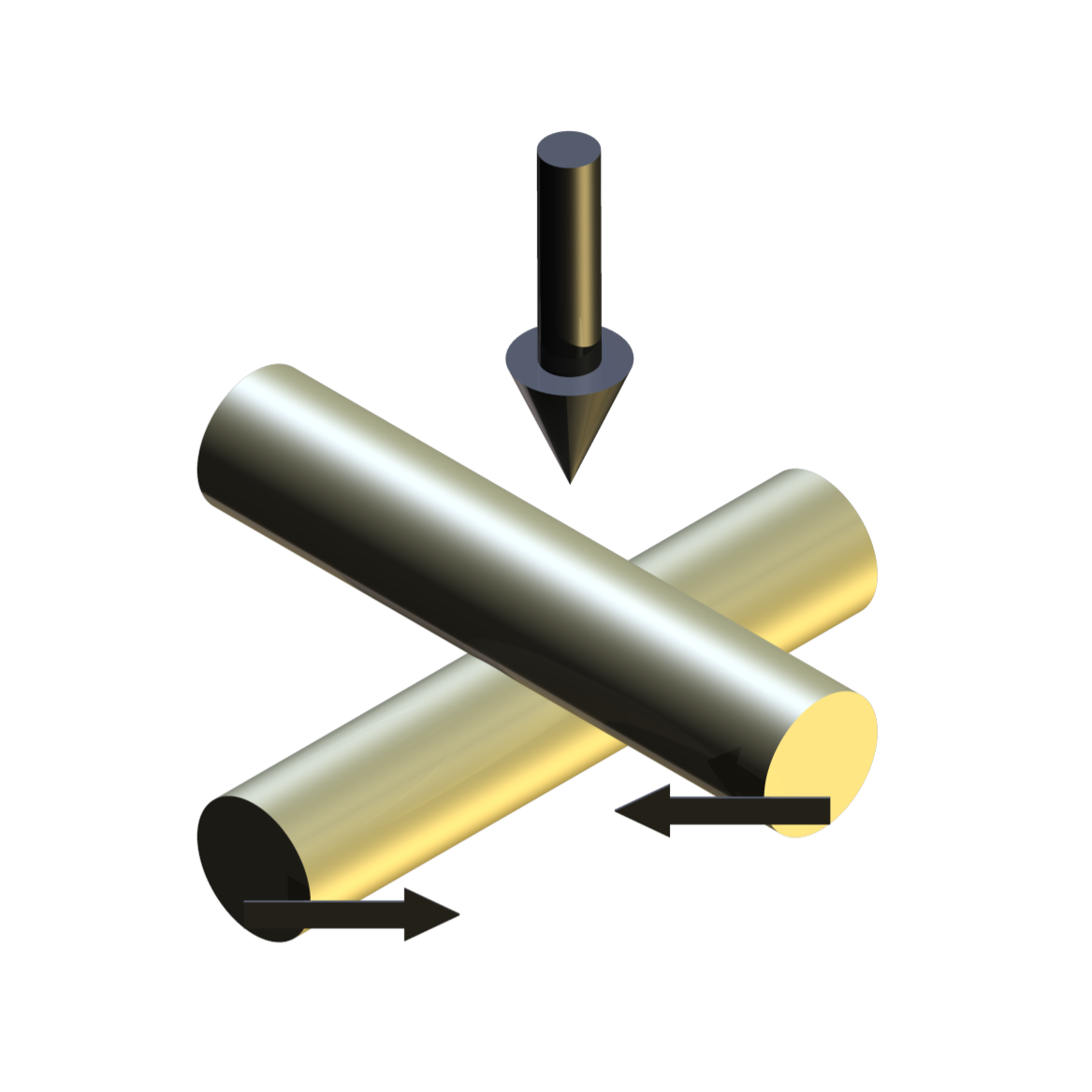
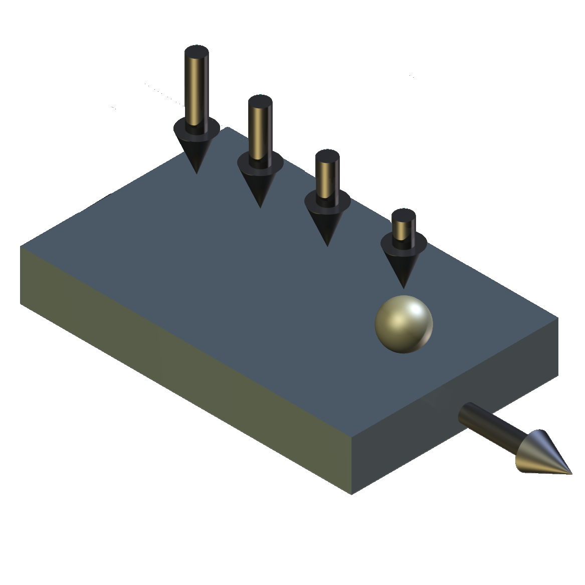
With the TE 69 Load Scanner geometry, the samples are indexed and the load applied by three independently controlled, but synchronised motion, actuators. Two elongated test specimens, preferably bars or rods, are used. The orientation of the test specimens and their relative sliding motion during testing is arranged in such a way that the contact spot moves along a contact path on each specimen; each spot along this path on one specimen will only make contact with one spot on the other specimen, and vice-verse. The contact spot is the area over which the contact load is distributed.
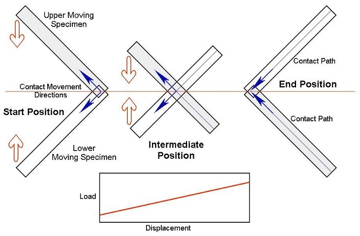
The relative motion is generated by two servo-controlled ball-screw actuators, with one connected to the lower specimen carriage and the other to the upper specimen carriage. The carriages are moved synchronously, in equal but opposite directions, so that the point of contact does not move relative to the machine.
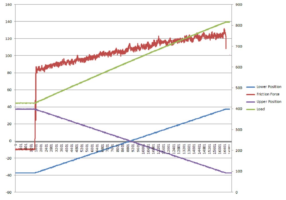
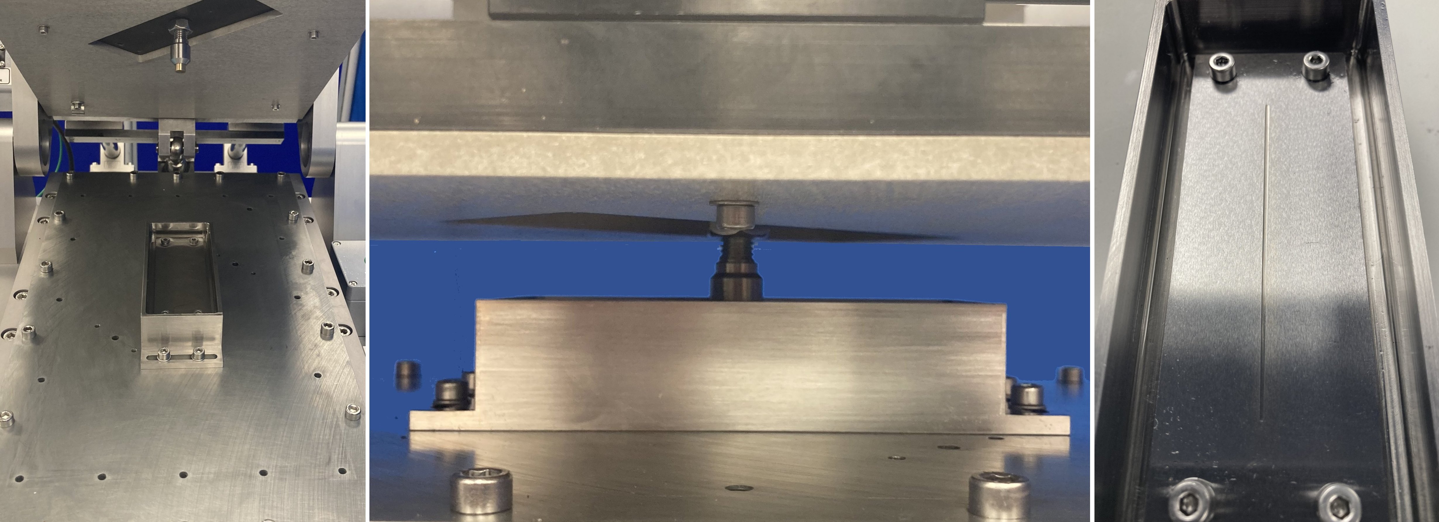
The upper specimen carriage is mounted on a pivoted lever arm and load is applied by means of a pulley mechanism and spring, connected between the arm and a third servo actuator. This allows control of the load profile, independent of the motion control. The system can also be programmed to apply a steady or increasing load on the forward stroke, but remove the load for the reverse stroke, thus producing repeated, unidirectional motion.Standard Load Scanner Applications
A single pass experiment resembles the test procedure often used in scratch testing of coated specimens. For coatings evaluation, it is normal to have one specimen coated and select the material from the practical application, for the counter specimen.
Reciprocating sliding tests, with stroke-wise load variation, can be used to produce conditions ranging from mild wear to scuffing, at different positions on a single pair of specimens.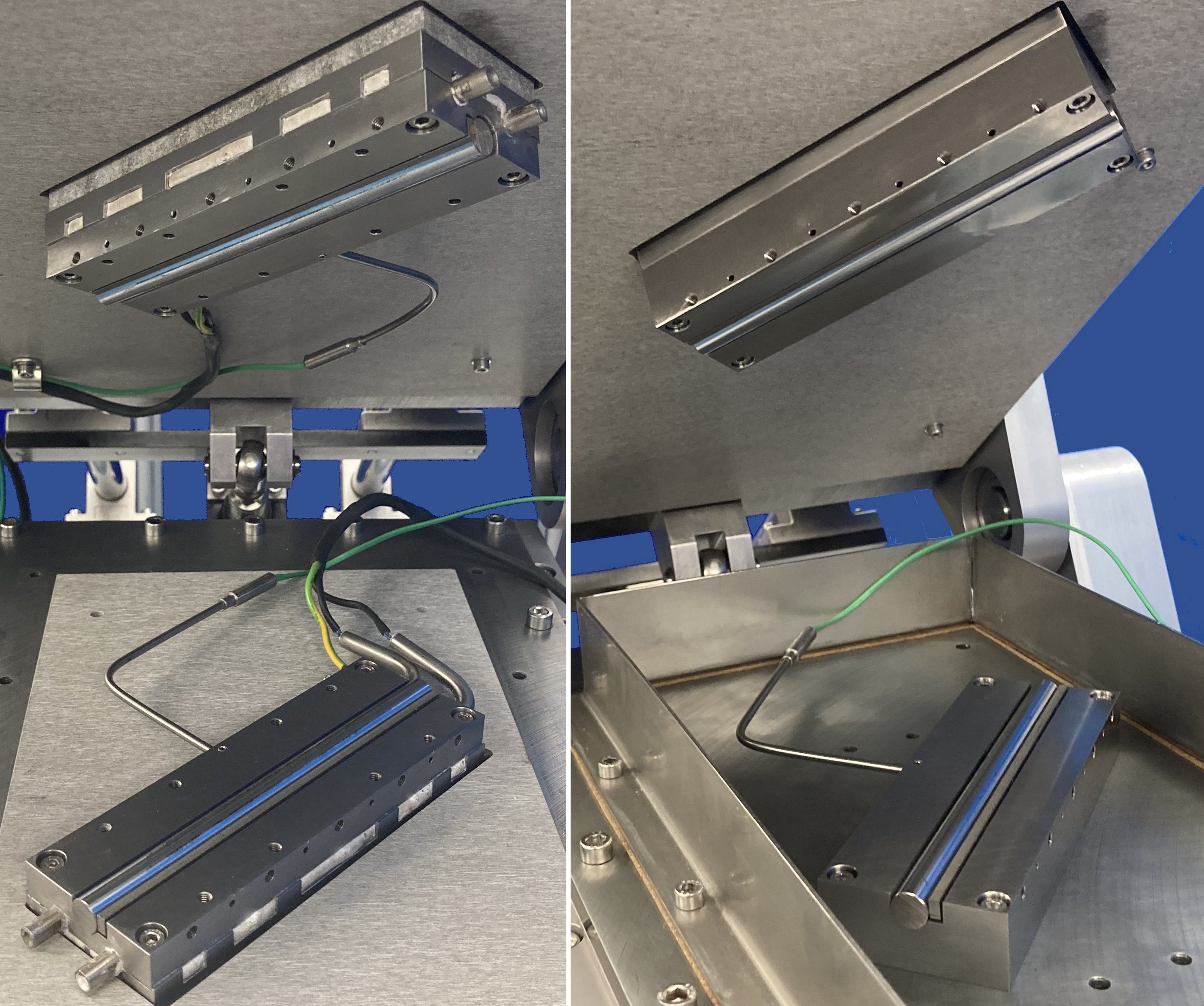
Tests may be run either dry, with the rod samples carried on individual heater blocks, or lubricated, with the lower rod sample carried in a heated lubricant bath.
Alternative Configurations
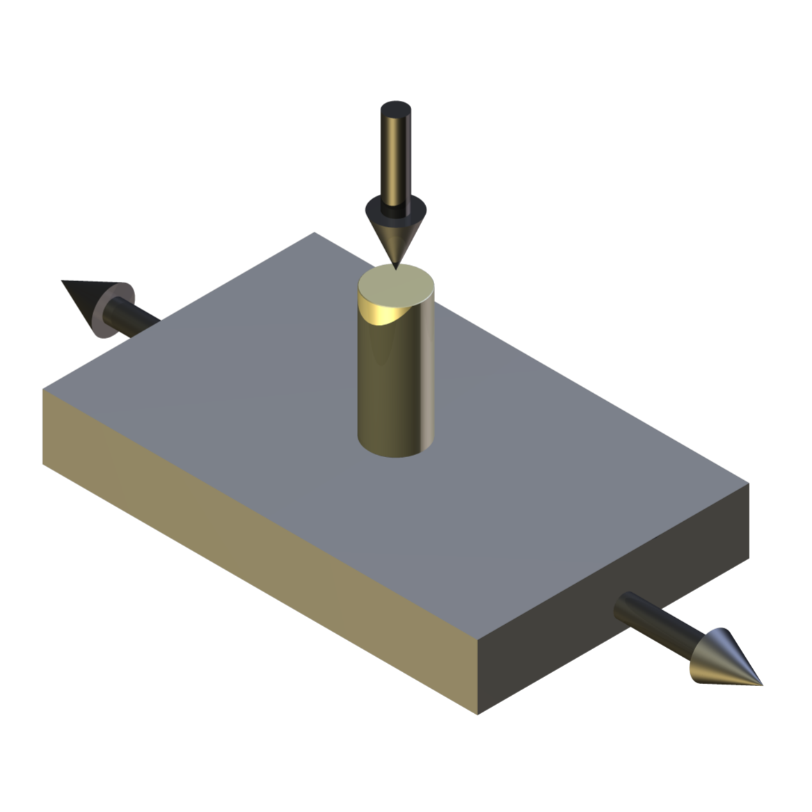
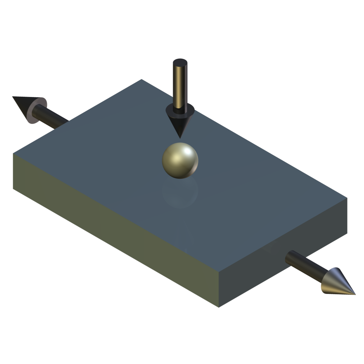
With the upper specimen carriage parked, the upper sample can be replaced by a pin or an indenter. The lower specimen can now be a plate and the machine used in reciprocating pin on plate mode.
Independent control of the load allows tests to be run with a steady state load, or with a ramped load as in a conventional scratch test.
Control and Data Acquisition
COMPEND 2000 control and data acquisition software, in conjunction with Phoenix Tribology’s own USB interface module, provides automatic control of load, speed, stroke length, temperature and test duration, combined with data logging of all measured parameters.
-
Technical Specifications
Contact Geometry: Crossed Cylinder on Cylinder Crossed Flat on Flat Pin on Plate Indenter on Plate Test Modes: Load scanner with ramped load Pin on plate with constant load Scratch test mode with ramped load Repeat scratch test with unloaded reverse stroke Maximum Load: 2000 N Tooling Clamps Unheated: 3.2 mm diameter and 12 mm diameter Tooling Clamps Heated: 3.2 mm diameter and 12 mm diameter Cylinder Length: 175 mm Wear Scar Length – Load Scanner: 100 mm Wear Scar Length – Pin on Plate: 75 mm Maximum Stage Travel: 75 mm (each) Maximum Repetition Rate: 0.3 Hz Lubricant Bath Temperature: Ambient to 250°C Upper Rod Specimen Temperature: Ambient to 600°C (dry tests only) Lower Rod Specimen Temperature: Ambient to 600°C (dry tests only) Load and Traverse Actuators (Qty: 3): Servo-controlled Ball Screw Dynamic Force: 700 N Static Force: 700 N Maximum Traverse Speed: 150 mm/s Load Arm Ratio: 5:1 Actuator Motors: 400 W Automatically Controlled Parameters Traverse Speed Bath Temperature (lubricated tests) Upper Specimen Temperature (dry tests) Lower Specimen Temperature (dry tests) Test Duration Mechanically Adjusted Parameters Starting Load Rate of Loading Recorded Parameters Traverse Speed Load Stroke Displacement Friction Force Bath Temperature (lubricated tests) Upper Specimen Temperature (dry tests) Lower Specimen Temperature (dry tests) Number of Cycles Test Duration Friction Coefficient Sliding Distance Services Electricity: 220/240V, single phase, 50 Hz, 3 kW 110/120 V, single phase, 60 Hz, 3 kW -
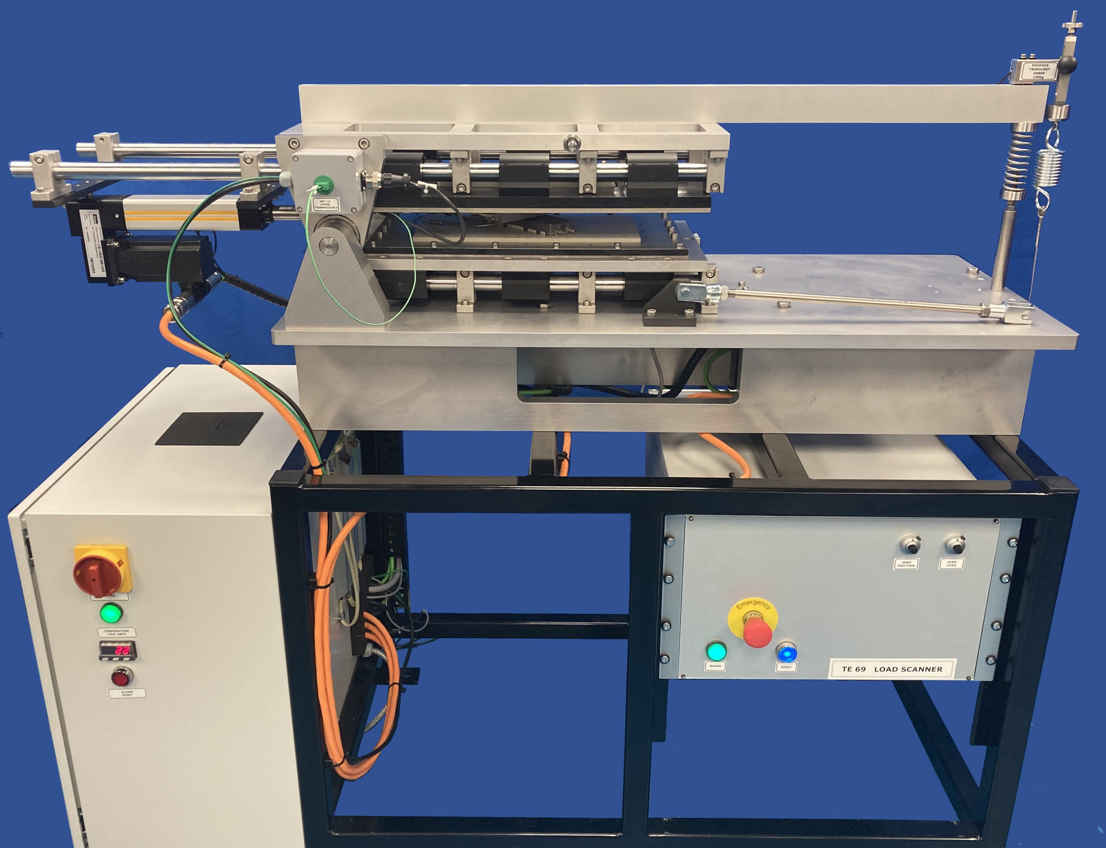
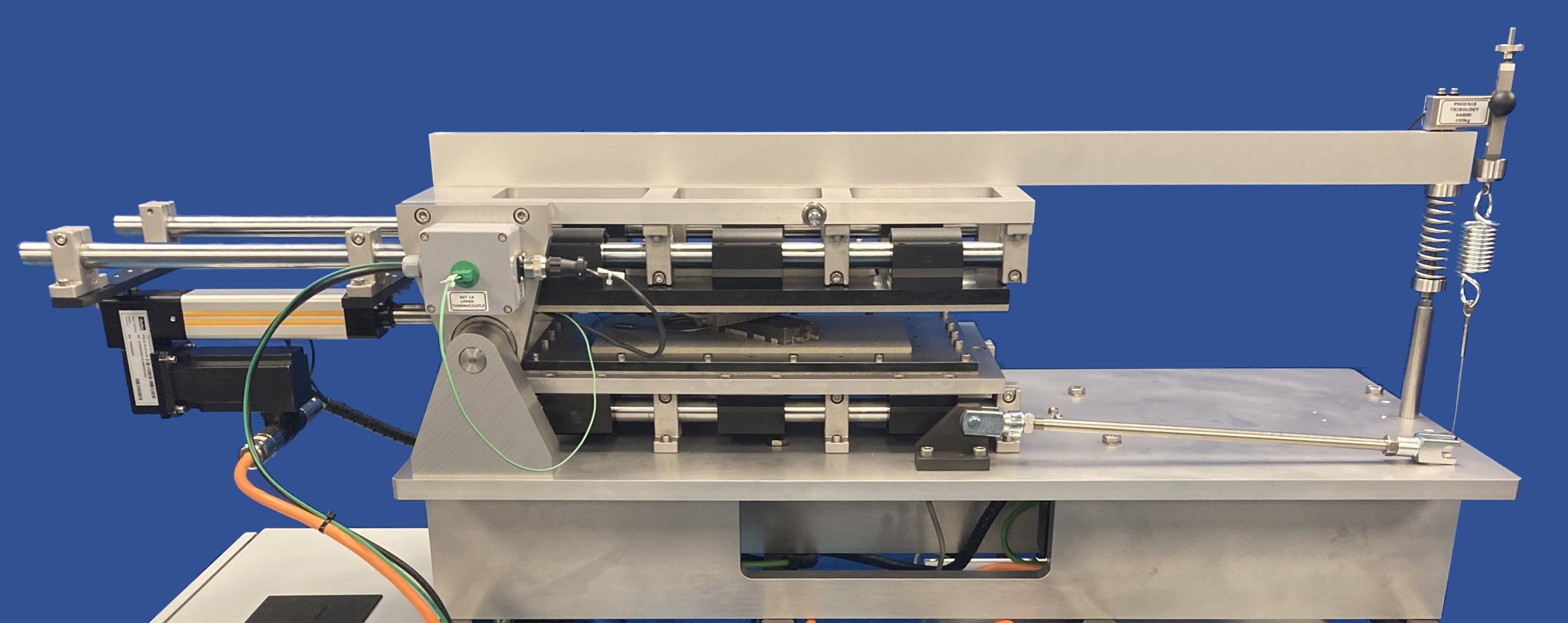
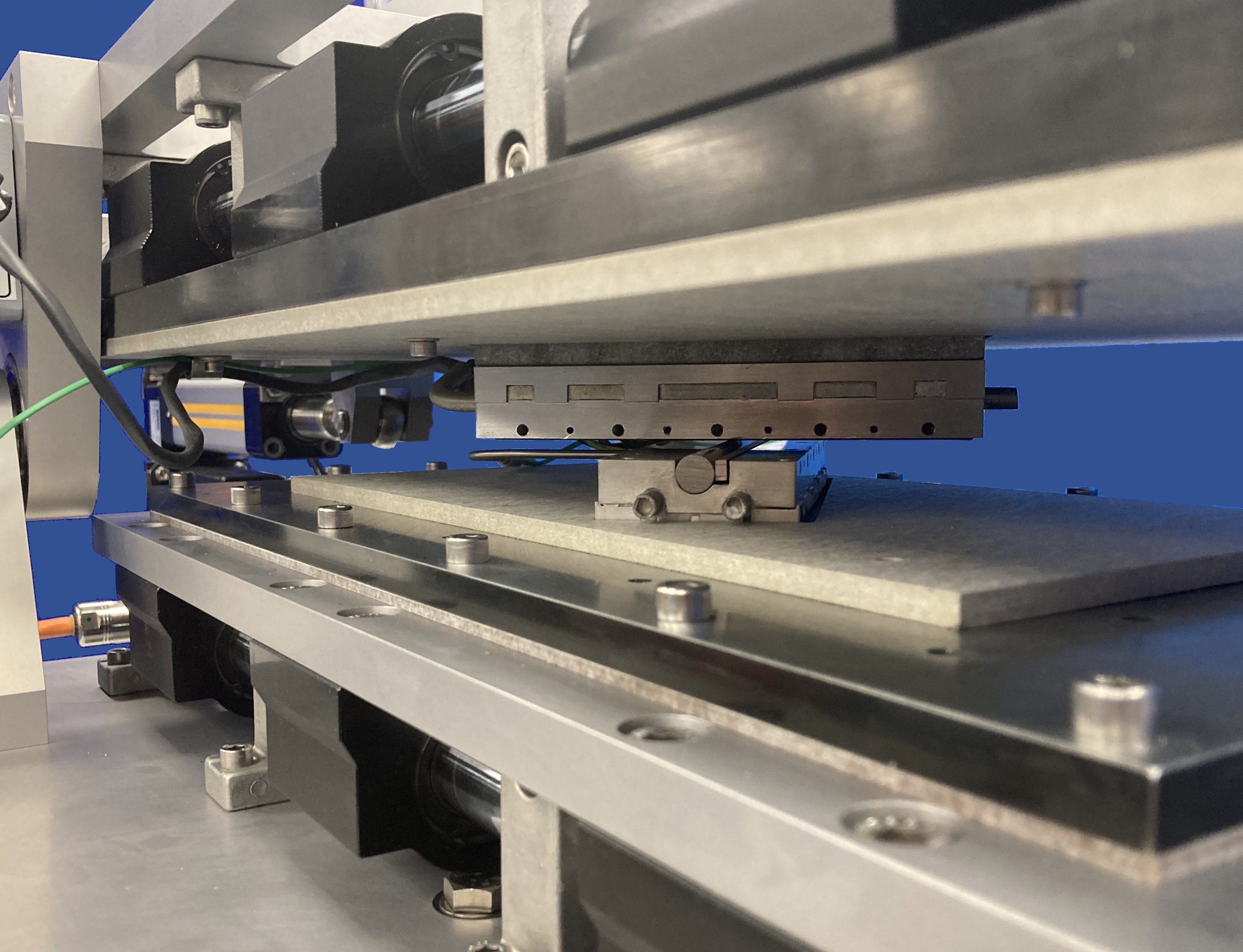
Machine Overview
-
Index Tags
-
Download the Machine Leaflet

Call us on +44 (0) 1635 298279
Email : info@phoenix-tribology.com
Email : info@phoenix-tribology.com