-
Introduction
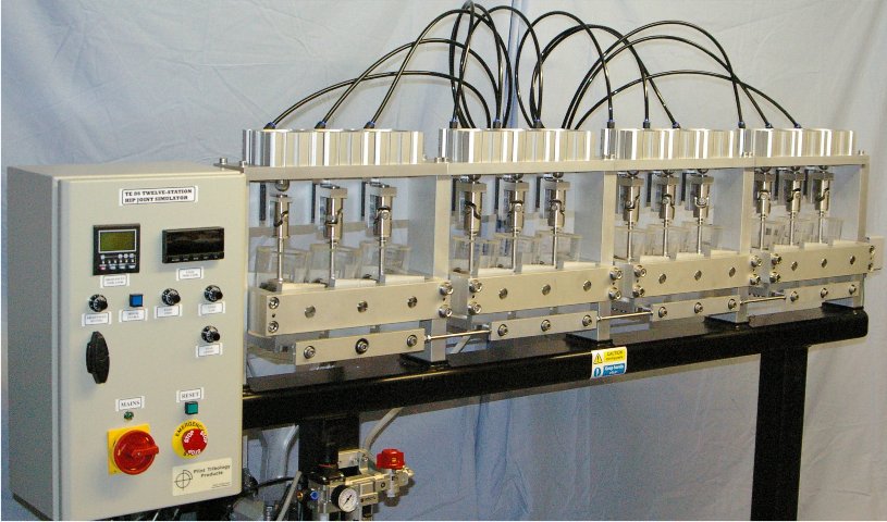
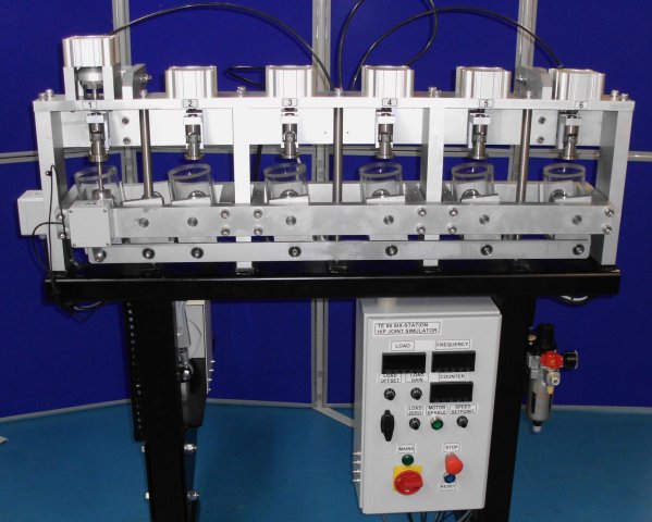
The TE 86 Multi-station Hip Joint Simulator is manufactured under licence from Dr Vesa Saikko, Laboratory of Machine Design, Department of Mechanical Engineering, Helsinki University of Technology. The device incorporates an electro-mechanical drive and servo-pneumatic loading system. The machine is simple to operate and a very cost-effective solution for multi-station wear testing of prosthetic hip joints. The unit is available with twelve test stations, with a maximum load of 2 kN per test station, or six test stations, with a maximum load of 3 kN per test station.
Description
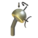
The TE 86 provides two-axis motion with the prosthesis samples mounted in the appropriate anatomical position. The acetabular cup is located above the femoral head so that in the neutral position, the symmetry axes of both the head and the cup are at an angle of 45 degrees to the vertical. This angle can be varied, if required, without difficulty, by varying the design of the tooling.
The two-axis motions, flexion-extension (FE) and abduction-adduction (AA), are nearly sinusoidal, and their phase difference is pi/2. As internal-external rotation has been shown to be unimportant in the simulation of clinical wear, this motion has been excluded.
The head is the moving component and the cup is stationary. The direction of loading is vertical and fixed relative to the cup. The load is dynamic, of double-peak waveform, and is monitored with a force transducer fitted to just one master test stations. The maximum, minimum, and average load values are 2.0 kN, 0.4 kN, and 1.2 kN, respectively.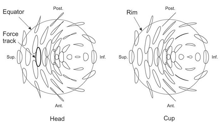
The force track on the femoral head is elliptical with an aspect ratio of 3.8, which has been shown to be a good representation of human gait. The length of the force track is 1.73r, where r is the head radius.
Loading and Driving System
The FE and AA motions are implemented electro-mechanically by means of a dual motion mechanical crank, driven by a fixed speed a.c. gear-motor. With a 50 Hz excitation frequency, the resulting test frequency is 1.06 Hz. An optional inverter drive can be supplied to allow tests to be performed at lower test frequencies or with different supply frequencies.
Each test station is loaded by means of a low volume pneumatic actuator. The actuators are connected to a common manifold. Air pressure to the manifold is controlled by means of a pneumatic regulator with integral pressure servo loop. The regulator is manually set to give the required peak load, which is measured by the force transducer fitted to the master test station. The measured load signal is thus used for monitoring only. The system is very stable in operation and subsequent manual adjustments are rarely necessary.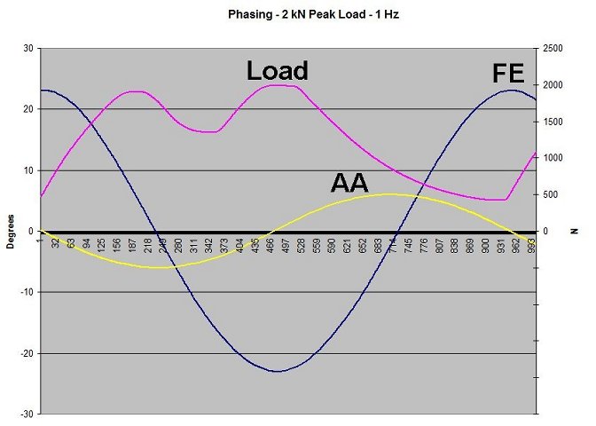
The load profile control signal for the pressure servo loop of the regulator is generated electro-mechanically by means of a cam, fitted to the output shaft of the gear-motor, acting on an LVDT fitted with a roller follower. The signal-conditioned output of the LVDT provides the demand set-point for the pneumatic regulator. This eliminates the requirement for a real-time control system, thus reducing the requirement for complex tuning, calibration procedures and waveform signal generator. The load profile can be modified, if required, by altering the cam profile and the phasing adjusted by rotating the cam on the output shaft.
Sample Mounting and Test Enclosure
Both the femoral and the acetabular components are easy to demount for periodic cleaning, examination and wear measurement. Quality tooling fixtures allow the test components to be reinstalled in exactly the same position for the continuation of the test. An important characteristic of the design is that any type of prosthetic hip joint can readily be tested.
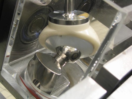
An acrylic lubricant chamber with a volume of 500 ml fits over the test components. The fluid volume is deliberately large in order to eliminate the possibility of overheating of serum-based lubricants.
-
Technical Specifications
Test Configuration: Acetabular cup on femoral head Number of Test Stations: 6 or 12 Test Frequency: 1.06 Hz (with 50 Hz supply) 1.27 Hz (with 60 Hz supply) Maximum Load: 3 kN (6 station) or 2 kN (12 station) Minimum Load: 0.4 kN Average Load: 1.2 kN Flexion-extension (FE): 46 degrees Abduction-adduction (AA): 12 degrees Force Track Aspect Ratio: 3.8 Force Track Length: 1.73r (where r is head radius) Motor Power: 370 W Fluid Volume: 500 ml Controlled Parameters Test Load Number of Cycles Services Electricity: 1.5 kW 240 volt 50 Hz single phase plus neutral 1.5 kW 110 volt 60 Hz single phase plus neutral Compressed Air: 4 cfm at 8 bar (typical) -
Index Tags
-