-
Description
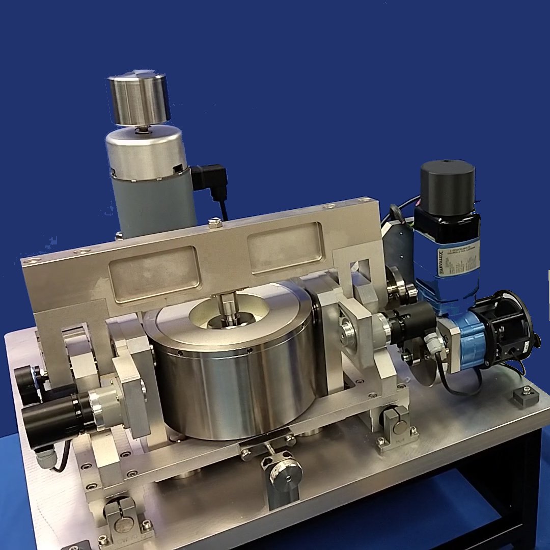
The key performance requirements for the Friction Simulator are that it applies a defined load cycle in a predictable and repeatable fashion and measures the very low levels of friction generated within the lubricated joint.
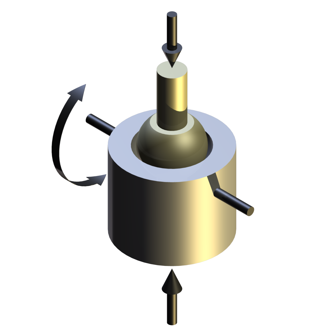
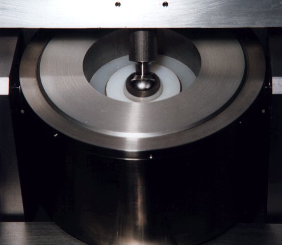
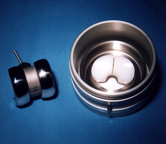
The machine comprises two support systems for the hip and knee joint components. Hip joints are inverted from their natural position. The acetabular cup or tibial plate component is mounted in a low friction trunnion mounted reservoir carried in a loading frame. The femoral component (either a taper mounted ball or special fixed axis knee piece) is mounted on the underside of a rigid cross-beam that is oscillated through an adjustable pre-set angle. A jig is provided to ensure that the femoral component is oscillated about its centre and is aligned with the lower test piece.Load and Torque Measurement Assembly
A high duty linear solenoid acting through a 9:1 lever applies the load to the carriage that supports the trunnion mounted reservoir. This system is compact, stiff and provides an easily controllable loading cycle. The load is measured by a piezo-electric force transducer mounted centrally on the carriage.
The trunnion bearings are mounted in such a way as to permit their inner races to be driven. Rotating the bearings increases their load carrying capacity from their static to their dynamic rating and reduces the parasitic friction from static to rolling friction. By driving the bearings in opposite directions the parasitic torque transmitted to the trunnion assembly by the bearings substantially cancels out. A parasitic torque of about 10% of the smallest measured friction torque is expected.
The trunnion mounted assembly is restrained from rotation by a piezo-electric force transducer carried on the lower loading carriage and connected by means of a flexure link.
Two reservoirs are provided, one for the acetabluar cup and one for the tibial plate. Tests may be run dry and lubricated with water, synthetic lubricants and synovial fluid.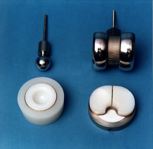
Driven Component Assembly
The cross beam carrying the femoral component is carried in bearings that are in line with the axis of the lower trunnion mounted assembly. These bearings are carried on brackets mounted on linear ball slides which allow the lower specimen assembly to be located correctly and locked in position.
The beam is oscillated sinusoidally through a crank mechanism with an adjustable throw. The mass of the arm and crank mechanism are minimised in order to minimise out of balance forces and thus to reduce the potential for parasitic excitation of other parts of the assembly. The drive arrangement comprises a thyristor controlled dc gear motor with tachogenerator feedback.
The timing between the load on/off action and the oscillating action is adjusted by means of an optical sensor and adjustable trigger. This permits the position of load and the duration of load application to be adjusted. It also permits the load to be applied on either the forward or reverse strokes.Control and Data Acquisition
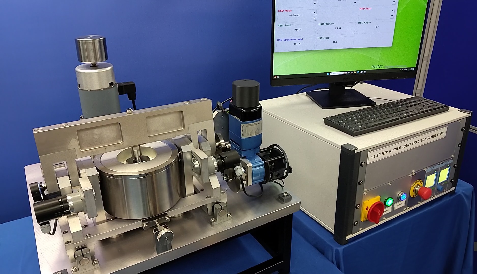
Control and data acquisition are implemented via host PC running COMPEND 2020 Windows compatible software, in conjunction with a Phoenix Tribology USB micro-controller interface.
Automatic control is implemented via user programmable test sequences. Manual control is implemented using on screen toggles. Data is stored to hard disc in either .csv or .tsv file formats. -
Technical Specifications
Load Range: 200 to 2,500 N Load Sensor: piezo-electric transducer highest sensitivity: 10 mN highest range: 7,500 N Frequency Range: 0.02 to 1 Hz Oscillating Angle: 0 to +/- 35 degrees Friction Sensor: piezo-electric transducer highest sensitivity: 1 mN highest range: 500 N Maximum Knee Size: 85 mm wide Interface: Phoenix Tribology USB micro-controller interface Software: COMPEND 2020 Controlled Parameters Applied Load Rotational Speed (Frequency) Number of Cycles Test Duration Measured Parameters Applied Load Rotational Speed (Frequency) Frictional Torque Number of Cycles Test Duration Services Electricity: 220/240V, single phase, 50 Hz, 3 kW 110/120 V, single phase, 60 Hz, 3 kW Installation Bench-mounting machine: 580 mm wide x 560 mm deep x 560 mm high Bench-mounting cabinet: 540 mm wide x 540 mm deep x 450 mm high Packing Specifications: 1.73 m3, GW 270 kg, NW 230 kg -
Machine Overview
-
Index Tags
acetabular cup artificial joints bioengineering materials bio-medical products femoral head hip and knee friction simulator knee prostheses prosthetic hip joints total hip replacement -